VCF 9.1: Deploying a Distributed Transit Gateway with a VNA Cluster
A practical VCF 9.1 lab walkthrough for deploying a Distributed Transit Gateway and Virtual Network Appliance cluster with routed external connectivity.
VMware Cloud Foundation 9.1 introduces a more distributed approach to VPC connectivity. Instead of depending on NSX Edge nodes for every routing requirement, a Distributed Transit Gateway (DTGW) can provide distributed routing at the ESX host layer through a VLAN-backed or VXLAN-backed external connectivity model.
In this lab, I deployed a DTGW with a Virtual Network Appliance (VNA) cluster and connected a VPC subnet to my physical network through a FortiGate firewall.
The goal was simple: provide routed connectivity for a VPC workload while keeping the forwarding path distributed and using the VNA only where stateful network services are needed.
Lab topology
The lab uses a VLAN-backed distributed connectivity design.
| Component | Value |
|---|---|
| VCF version | VCF 9.1 |
| Connectivity type | Distributed VLAN |
| External VLAN | VLAN 90 |
| FortiGate interface | 192.168.90.254/24 |
| External IP block | 192.168.90.0/24 |
| Private transit gateway IP blocks | 172.31.255.0/24 |
| Private VPC IP CIDR | 10.150.151.0/24 |
| Gateway type | Distributed Transit Gateway |
| Stateful services | VNA cluster |
The ESX uplinks and VNA interfaces must carry VLAN 90 end-to-end. This is essential: if the VLAN is missing from one trunk or mapped incorrectly, traffic can fail before it ever reaches the upstream firewall. Physical VLANs should be consistently available across the ESX host uplinks.
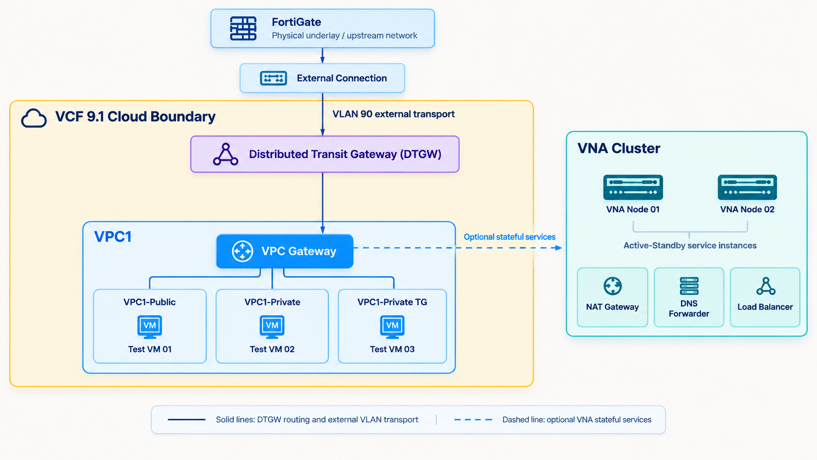 Architecture overview
Why use DTGW and VNA?
The DTGW handles distributed packet forwarding for connected VPCs. This removes the need to force every workload packet through a central routing appliance for basic routed connectivity. The Distributed VLAN Connectivity Model is designed to enable VPC-based networking without requiring a traditional NSX Edge deployment for that connectivity model.
The VNA cluster has a different responsibility. It provides a location for stateful services when they are required, such as NAT, DNS forwarding, load balancing, or VPN-related functions. Keeping distributed forwarding and stateful processing separate helps create a simpler and more scalable design.
Step 1: Prepare the physical network
Before creating anything in vCenter, confirm the physical network is ready.
- Create or identify the external VLAN. In this lab, this is VLAN 90.
- Ensure VLAN 90 is permitted on the switch trunks connected to every participating ESX host.
- Ensure the VLAN is also available to the VNA placement network.
- Configure the FortiGate interface for VLAN 90 with the interface IP.
My FortiGate interface uses the following address:
1
192.168.90.254/24
At this stage, verify basic Layer 2 and Layer 3 reachability from the VNA network toward the FortiGate.
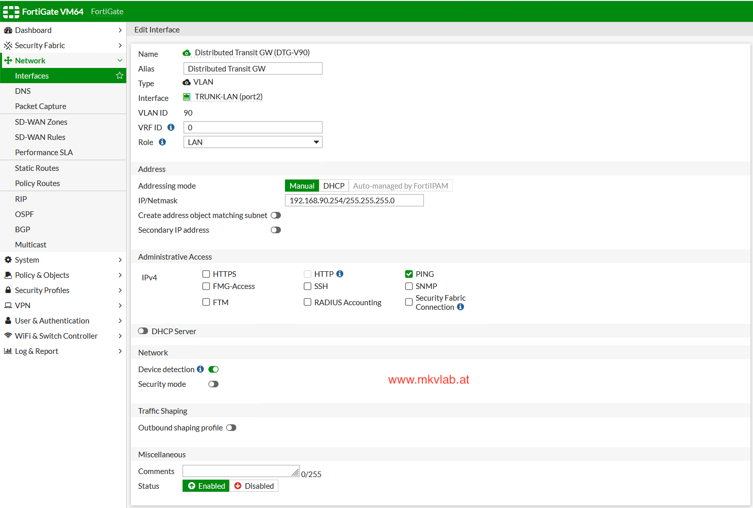
Step 2: Deploy the VNA cluster
In vCenter, open:
1
vCenter Server > Configure > Networking > VNA Clusters
Create a VNA cluster and select the relevant vSphere cluster for placement. Ensure that the deployed VNA instances are healthy before continuing.
The VNA cluster is not a replacement for the DTGW. Think of it as the service-processing component: the DTGW routes traffic in a distributed manner, while the VNA is used when traffic must pass through a stateful service.
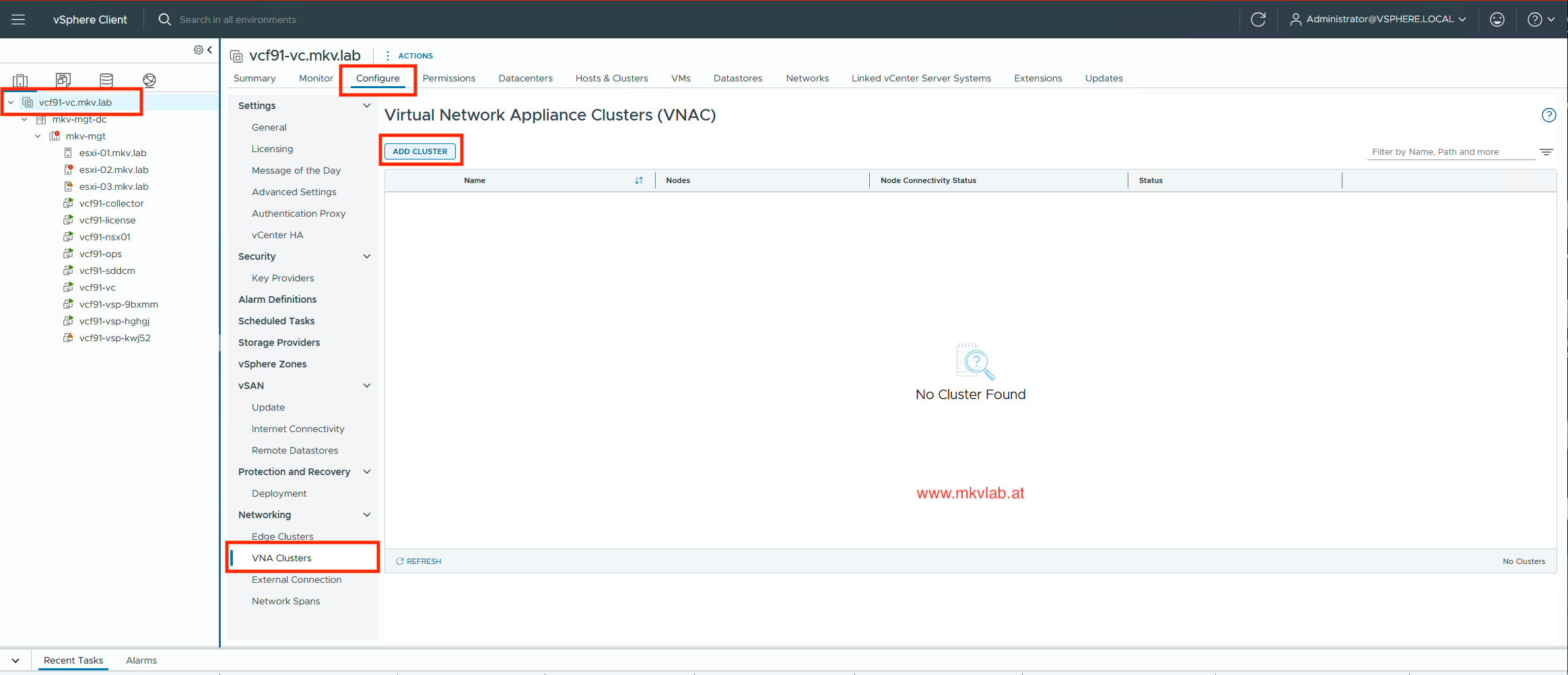 VNA Cluster
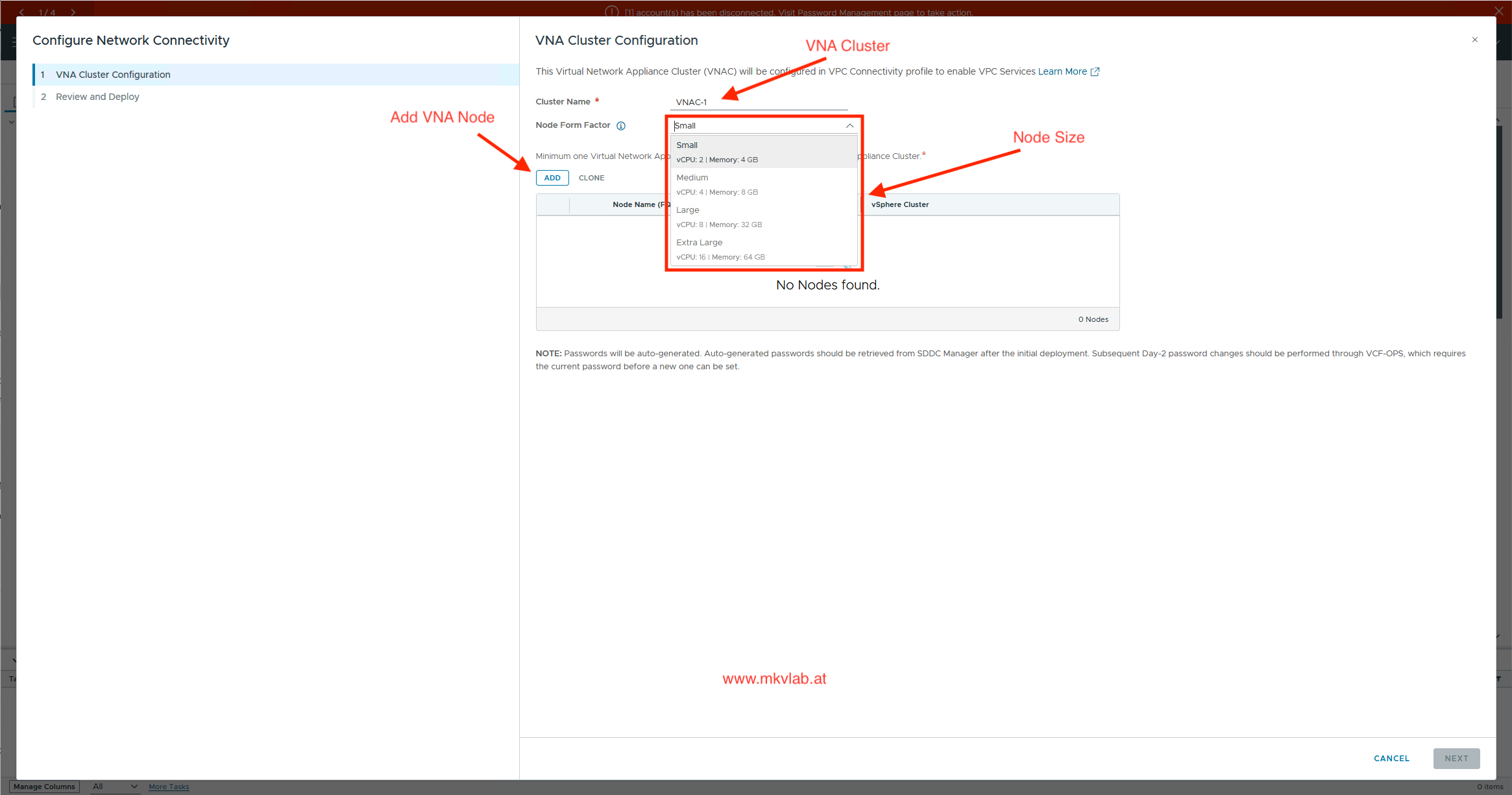 VNA Cluster Configuration
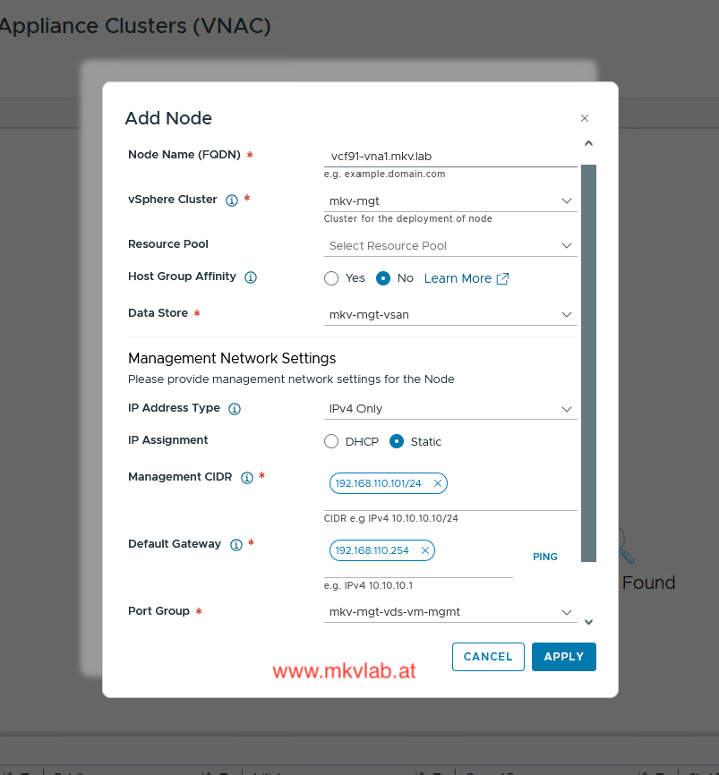 VNA Node
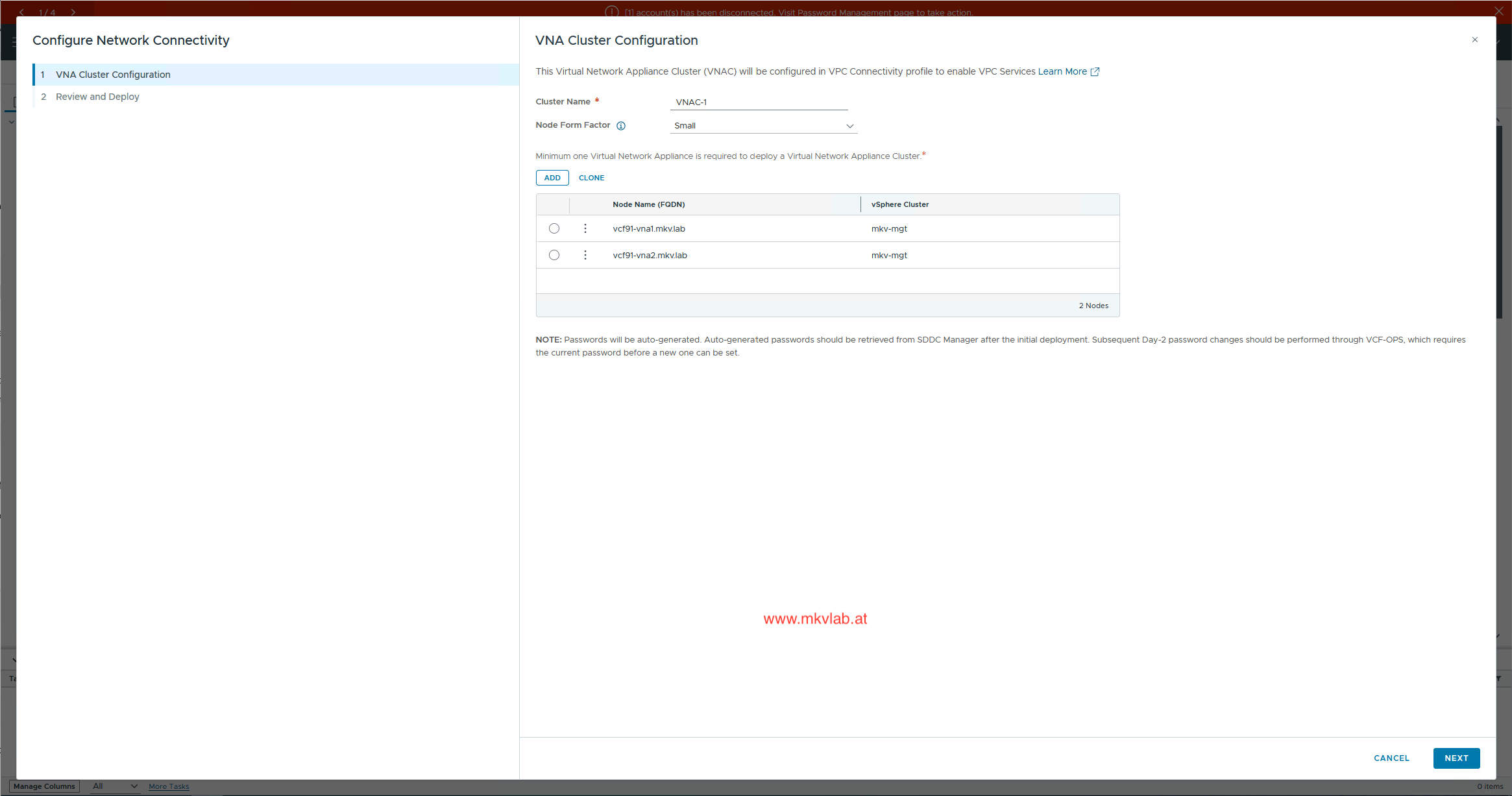 VNA Cluster Configuration
Step 3: Create the external connection
Create a VLAN-backed external connection for the DTGW.
Use the following example values:
| Setting | Example |
|---|---|
| Connection type | Distributed VLAN |
| VLAN ID | 90 |
| External network | FortiGate-connected VLAN |
| External IP block | 192.168.90.0/24 |
| Upstream gateway | 192.168.90.254 |
Use IP ranges that do not overlap with existing management, vMotion, NSX, VTEP, VPC, or physical network prefixes. Overlapping address ranges are one of the easiest ways to create routing problems that are difficult to troubleshoot later.
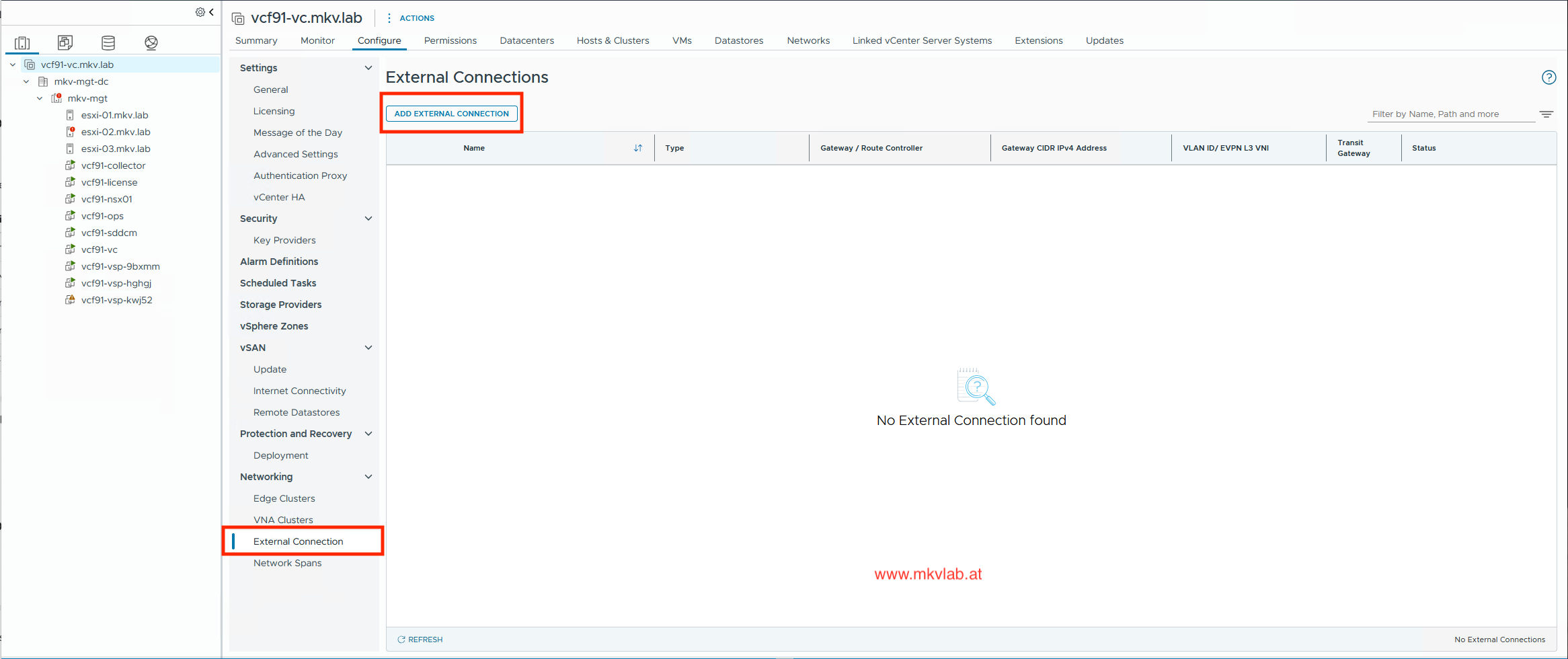 Add External Connection
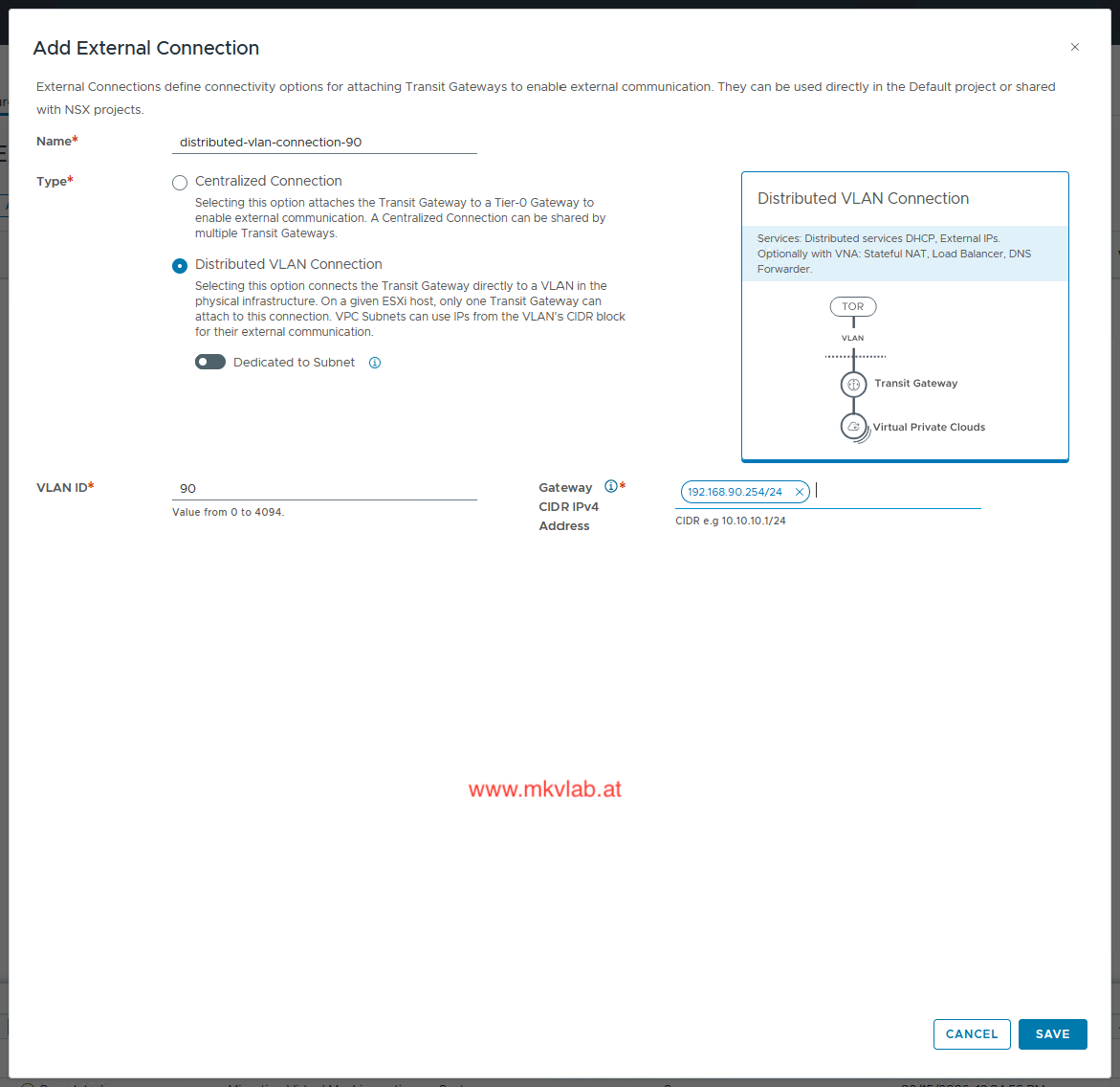 Distributed VLAN Connection
Step 4: Create the required IP blocks
Before creating the Distributed Transit Gateway, define the address pools that VCF can allocate for external connectivity and private transit connectivity.
For this lab, I created two IP blocks:
| IP block | IP Subnet | Purpose | Example design |
|---|---|---|---|
| External IP block | 192.168.90.0/24 | Provides addresses for public VPC subnets and external-facing services. This range must be routable in the physical network. | A dedicated routed subnet available through the FortiGate |
| Private Transit Gateway IP block | 172.31.255.0/24 | Provides internal addresses used for private transit connectivity between the DTGW and VPCs. This range must remain separate from workload and external subnets. | A dedicated non-overlapping private subnet |
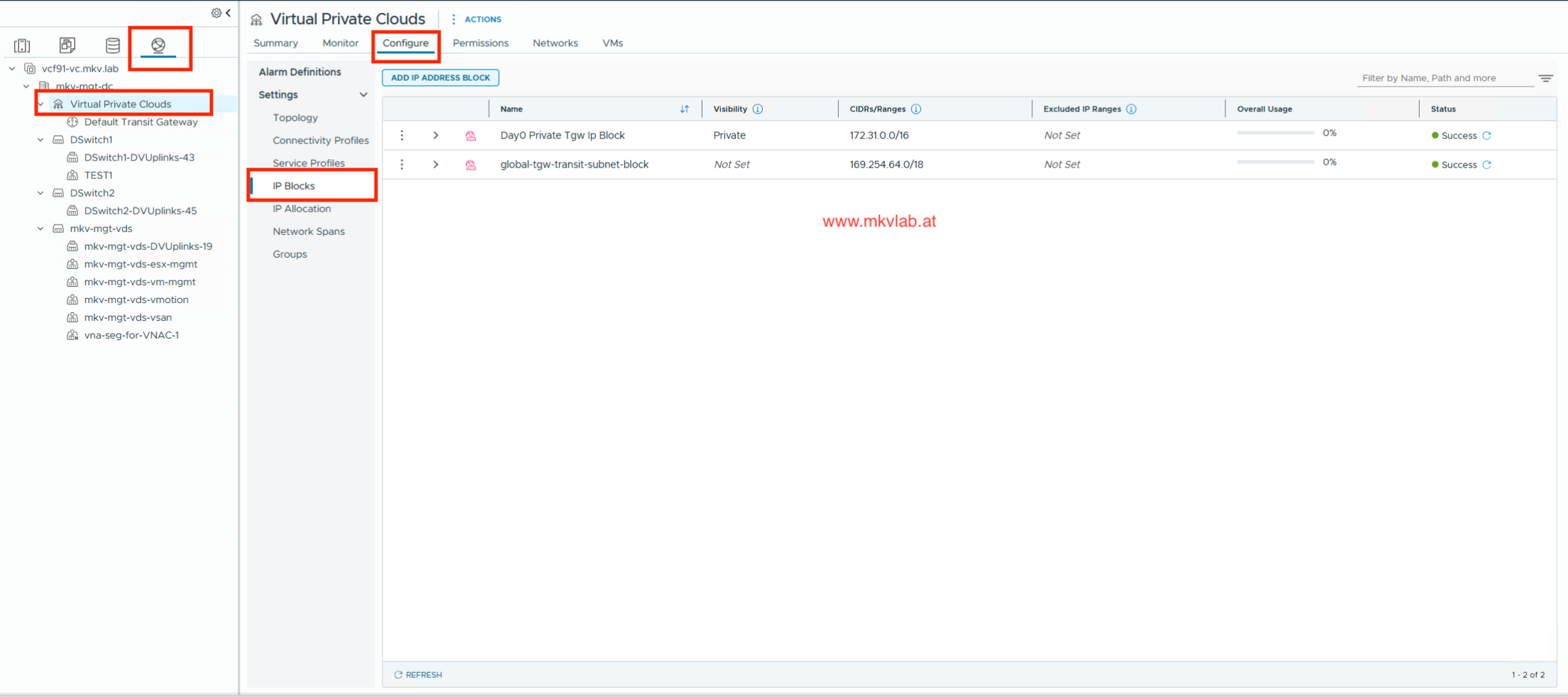 Add IP Address Block
Create the external IP block
Create an external IP block from the provider networking area and assign a range that is reachable from the physical underlay.
This block is used when VPCs consume public subnets or when a stateful service, such as NAT, requires an externally routable address. External IPv4 blocks selected for a VPC must be routable from outside that VPC.
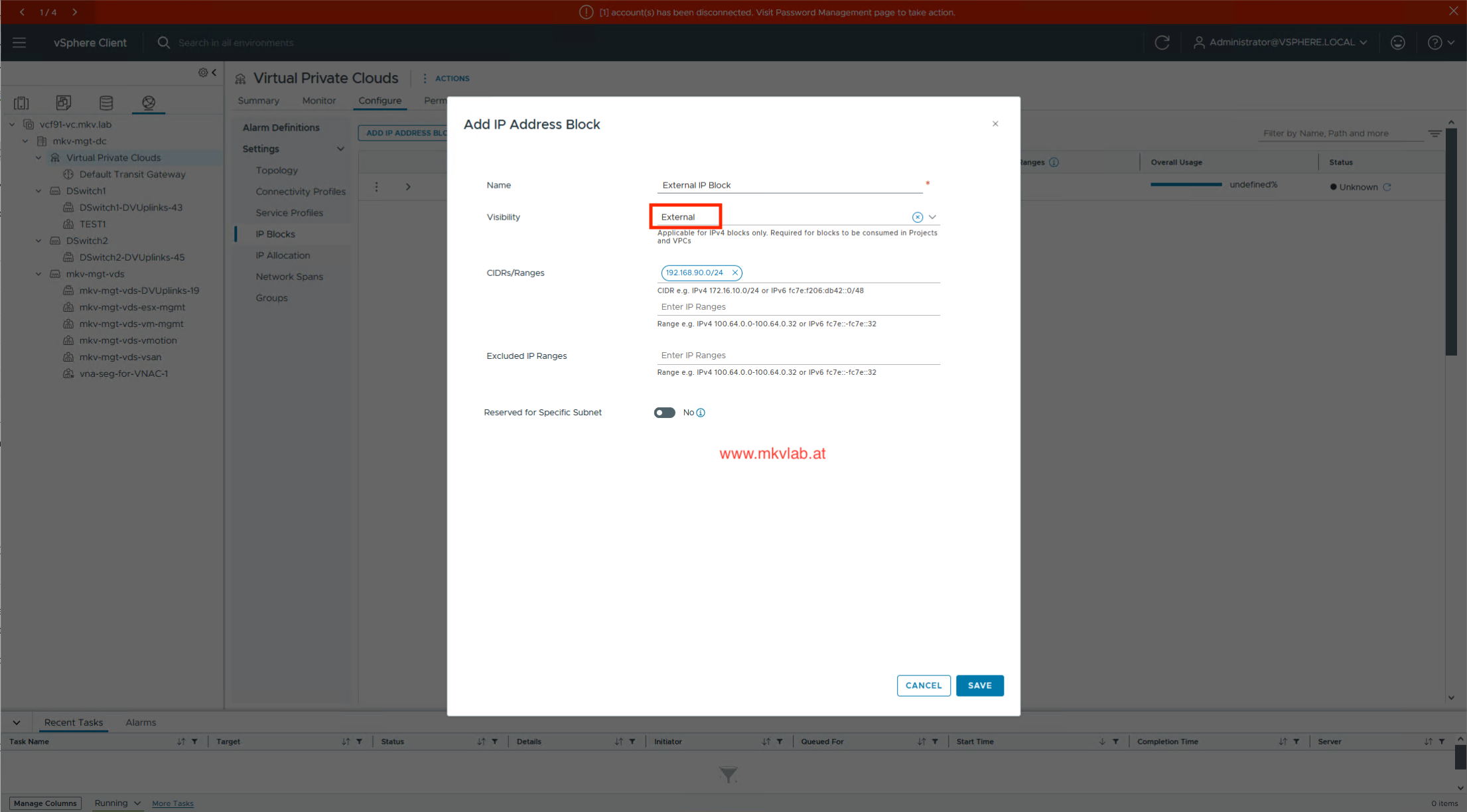 External IP Block
Create the Private Transit Gateway IP block
Next, create a Private Transit Gateway IP block.
This range is used internally by the distributed transit design. It should be private, dedicated to this purpose, and not advertised unnecessarily into the physical network.
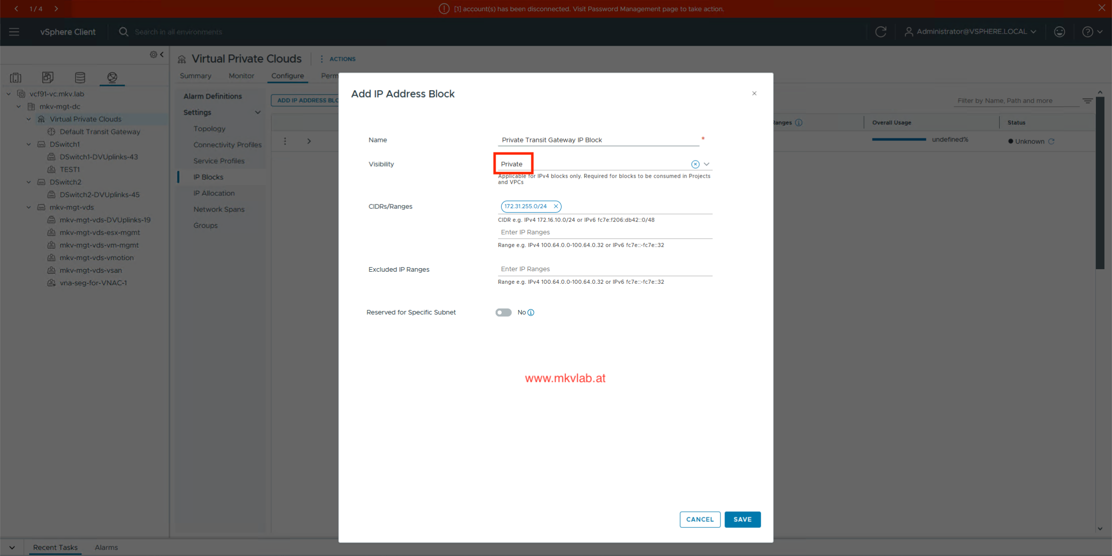 Private Transit Gateway IP Block
Important: Plan the address ranges before deploying the DTGW. Changing address design later can create avoidable routing, NAT, and service-migration work.
Step 5: Create the Distributed Transit Gateway
Create a new Transit Gateway and select the distributed connectivity option.
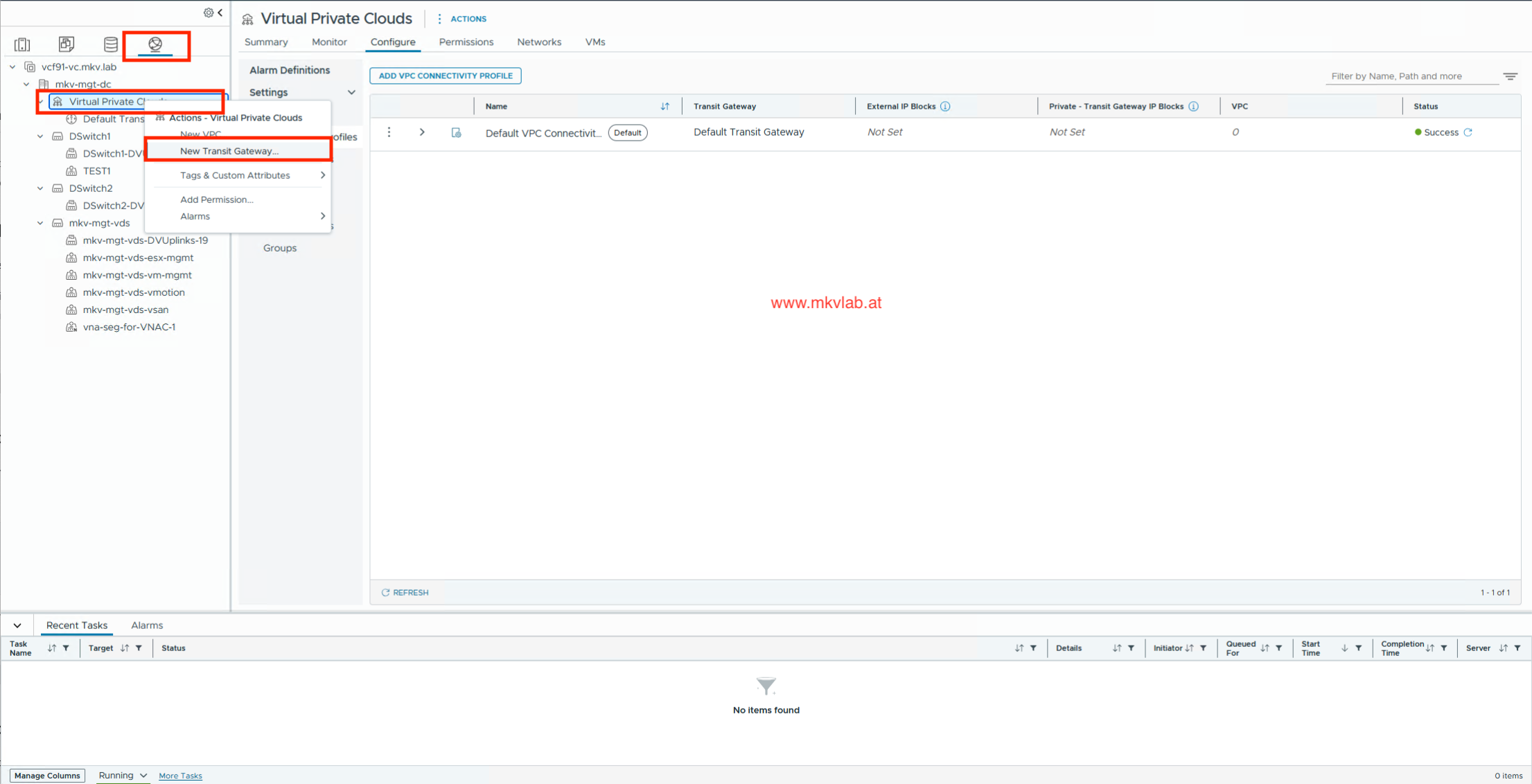 New Transit Gateway
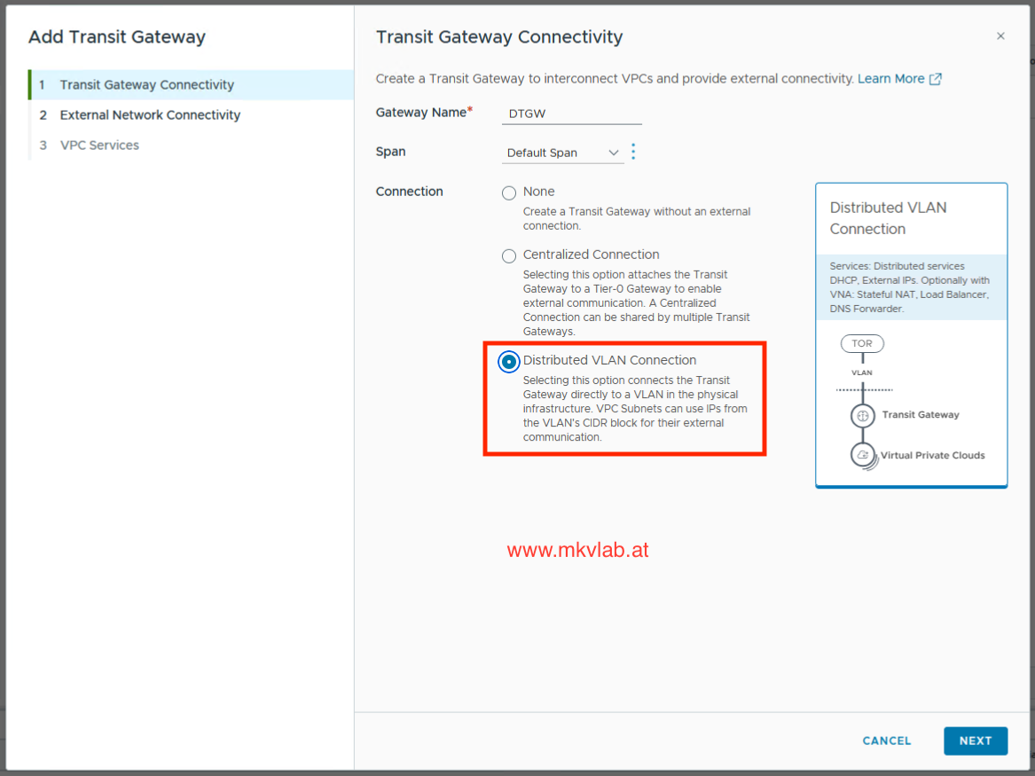 Distributed VLAN Connection
Attach the previously created external connection and select the VNA cluster where stateful services are required. VCF Automation supports creating and managing transit gateways that connect VPCs.
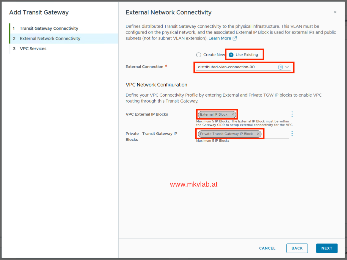 External Network Connectivity
And assign the VNA Cluster which has been created in previous step.
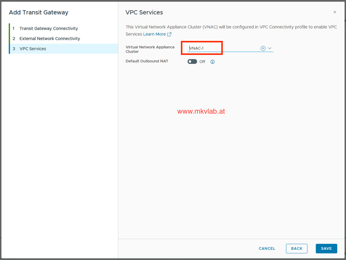 VPV Service
Note: Default Outbound NAT
Default Outbound NAT is optional. Enable it when workloads in private VPC or private transit subnets need outbound connectivity while sharing an address from the external IP block. VCF automatically creates source-NAT rules and sends matching stateful NAT traffic to the VNA cluster.
Step 6: Create the VPC and workload subnet
Create a VPC and attach it to the DTGW.
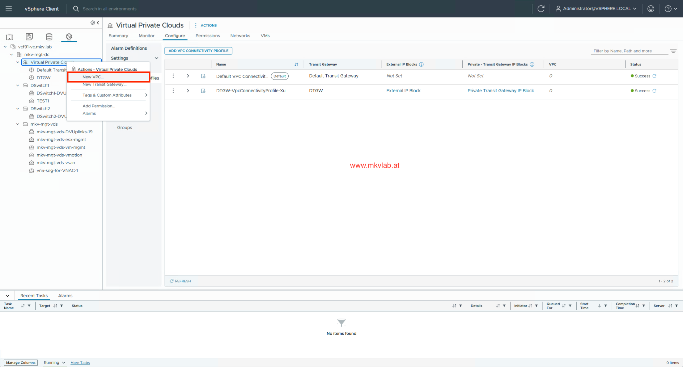 Creat New VPC
Here we need to define the Private VPC IP CIDRs and assign it to previously created Transit Gateway.
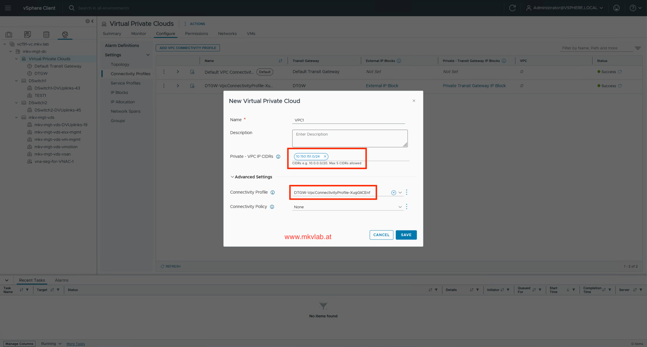 New Virtual Private Cloud
After creating the VPC1 and connecting it to the Distributed Transit Gateway, create the workload subnets required by the application design. In this lab, VPC1 contains a public subnet, a private subnet, and a private transit gateway subnet. Each type has a different role.
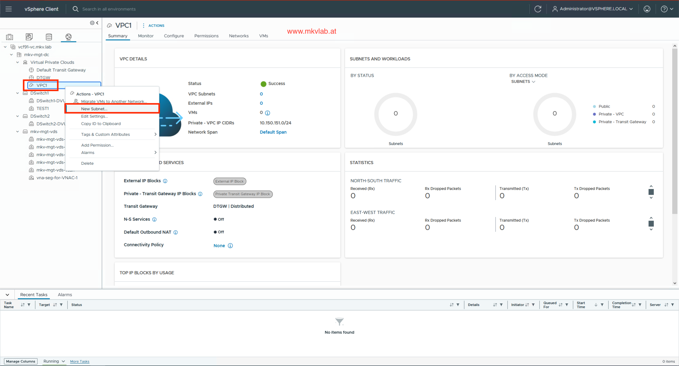 New VPC Subnet
Public subnet
Use a public subnet for workloads that require direct routed connectivity to the external network. Addresses are allocated from the external IP block, and the workload also will be accessible from outside.
In this lab, VPC1-Public is used for workloads that need to be reachable through the physical network. Default Outbound NAT is not required when the subnet is routed directly through the FortiGate.
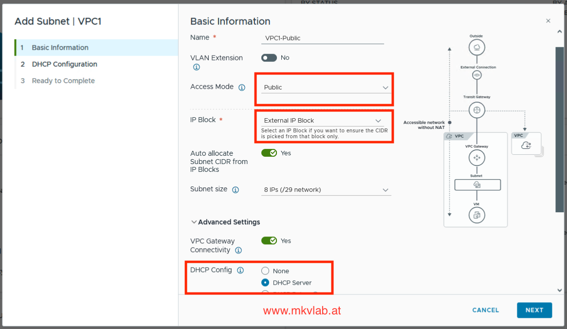 Public Subnet
Private subnet
Use a private subnet for internal application workloads that should not receive externally routable addresses. Typical examples include application servers, databases, internal services, and management components.
Workloads in VPC1-Private can communicate with other connected VPC networks according to routing and firewall policies. For outbound access beyond the VPC, use explicit Assign External IP or enable Default Outbound NAT when shared egress through the external IP block is required.
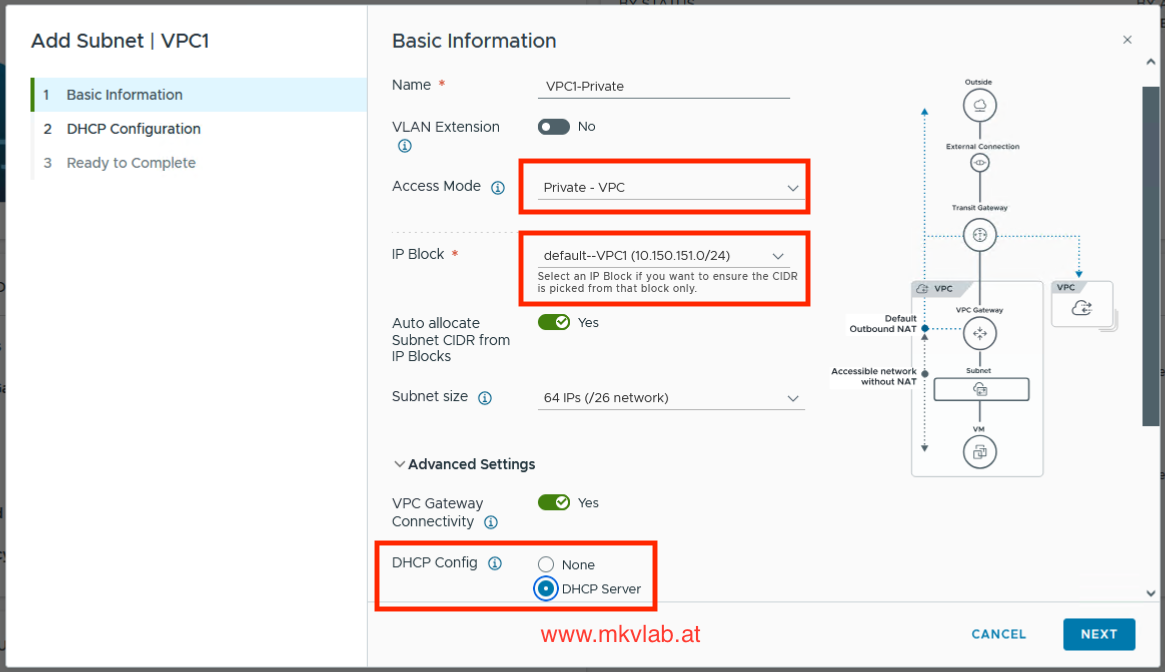 Private Subnet
Private transit gateway
A Private Transit Gateway subnet is a specialized virtual network network that routes traffic centrally through a Transit Gateway to enable secure communication between multiple connected Virtual Private Clouds (VPCs).
Ideal for hosting centralized resources — such as Active Directory, DNS, or CI/CD tools—that multiple application VPCs need to access. If you need external access in this network, you can also assign external IP or if the Default Outbound NAT is enabled, the subnet will also automatically have SNAT created.
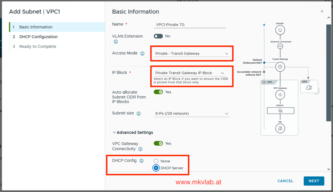 Private Transit Gateway Subnet
Here is the overview of all created subnets.
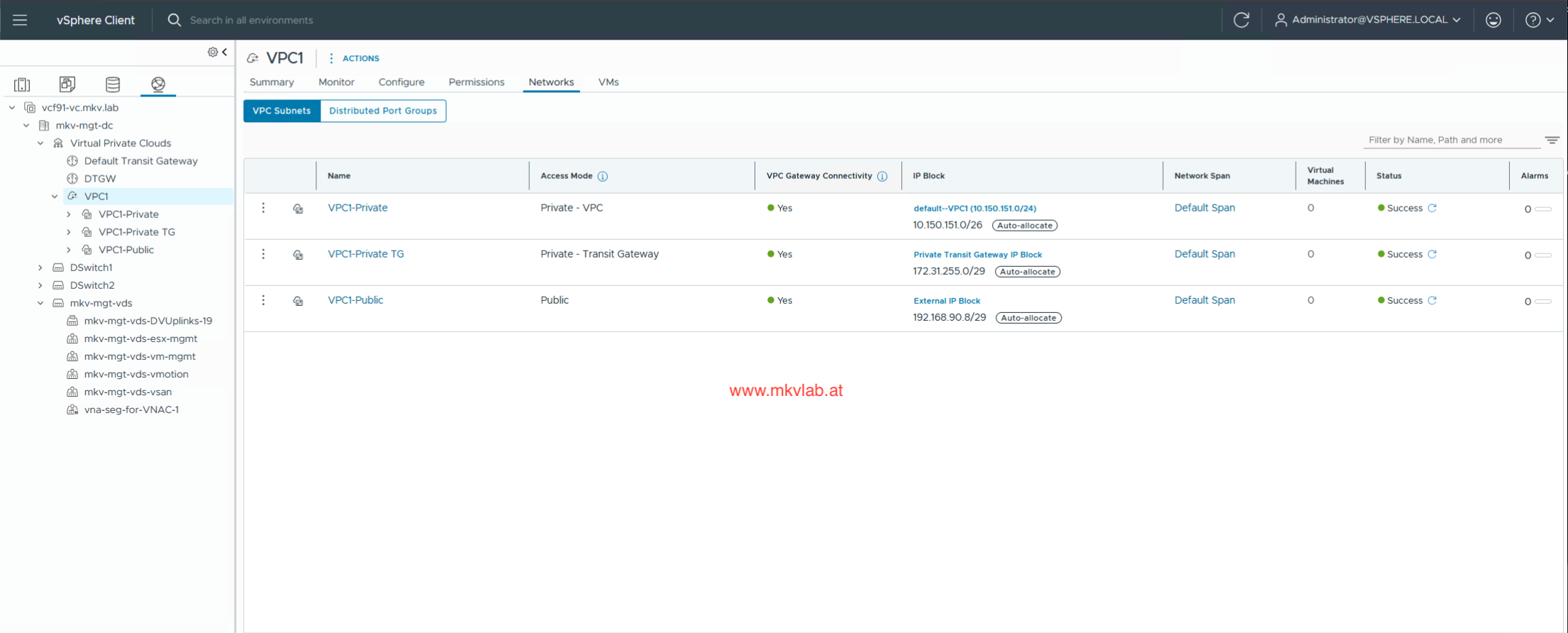 Subnets Overview
And here you can see the VPC topology.
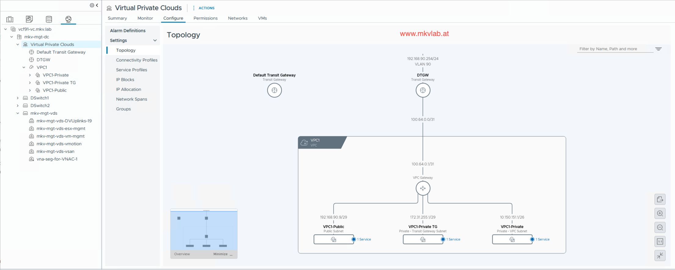 VPC Topology
Key takeaways
- DTGW provides distributed routing for VPC connectivity.
- A VNA cluster is used when stateful network services are required.
- VLAN consistency across physical switches, ESX uplinks, and VNA connectivity is critical.
- A routed VPC subnet does not always need default outbound NAT.
The distributed connectivity model is a good fit for environments that want VPC-based networking while integrating directly with an existing VLAN-based physical network. It offers a practical migration path toward VPC consumption without requiring all connectivity to traverse centralized Edge nodes.
Youtube Video
Here is my Youtube video demostrating DTGW deployment with VNA: