VCF 9.1: Deploying a Centralized Transit Gateway with NSX Edge
A practical VCF 9.1 lab walkthrough for deploying an NSX Edge cluster, configuring Tier-0 BGP connectivity, and connecting a VPC through a Centralized Transit Gateway.
In my previous post, I deployed a Distributed Transit Gateway (DTGW) with a Virtual Network Appliance cluster. That design keeps basic VPC forwarding distributed and uses the VNA when stateful services are required.
This time, I am taking the centralized approach. In this lab, I deploy an NSX Edge cluster, configure a Tier-0 Gateway with two external uplinks and BGP neighbors, and then create a Centralized Transit Gateway (CTGW) to provide external connectivity for a VPC.
The goal is to connect a VPC to the physical network through an Edge-backed Tier-0 Gateway and make the required routes available through BGP.
Lab topology
| Component | Lab value |
|---|---|
| VCF version | VCF 9.1.1 |
| Connectivity type | Centralized Connection |
| NSX Edge cluster | Edge-Cluster |
| NSX Edge node | edge-a |
| Edge TEP VLAN | 111 |
| Tier-0 Gateway | T0 |
| Left uplink segment | Left-Uplink, VLAN 117 |
| Left Tier-0 interface | 192.168.117.11/24 |
| Left BGP neighbor | 192.168.117.254 |
| Right uplink segment | Right-Uplink`, VLAN 118 |
| Right Tier-0 interface | 192.168.118.11/24 |
| Right BGP neighbor | 192.168.118.254 |
| Tier-0 local AS | 300 |
| BGP neighbor remote AS | 200 |
| VPC external IP block | External IP Block 92 — 192.168.92.0/24 |
The two uplink VLANs must reach the Edge node through its host uplinks. The Edge management network and TEP network must also be available before the Tier-0 and CTGW configuration can work correctly.
Note: This lab shows a single Edge node. Although the Tier-0 configuration uses Active-Active mode, a one-node Edge cluster does not provide node-level redundancy. For a resilient deployment, size and place additional Edge nodes according to your design.
Why use a CTGW?
A Centralized Transit Gateway connects VPCs to an external network through a Tier-0 Gateway backed by an NSX Edge cluster. In this design, the Edge infrastructure provides the centralized north-south connectivity path.
That is the main difference from the distributed VLAN design in my earlier post:
| Design element | DTGW with VNA | CTGW with NSX Edge |
|---|---|---|
| External connection | Distributed VLAN connection | Centralized connection through Tier-0 |
| Stateful service component | VNA cluster | NSX Edge cluster |
| Upstream routing in this lab | FortiGate-connected VLAN | Tier-0 BGP neighbors |
| Main configuration focus | Distributed connectivity and VNA services | Edge placement, uplinks, Tier-0 routing, and route redistribution |
Step 1: Deploy the Edge cluster
In the vSphere Client, select the vCenter Server and navigate to:
1
Configure > Networking > Edge Clusters
Select Add Cluster. In my lab, I named the cluster Edge-Cluster and added one Edge node, edge-a.
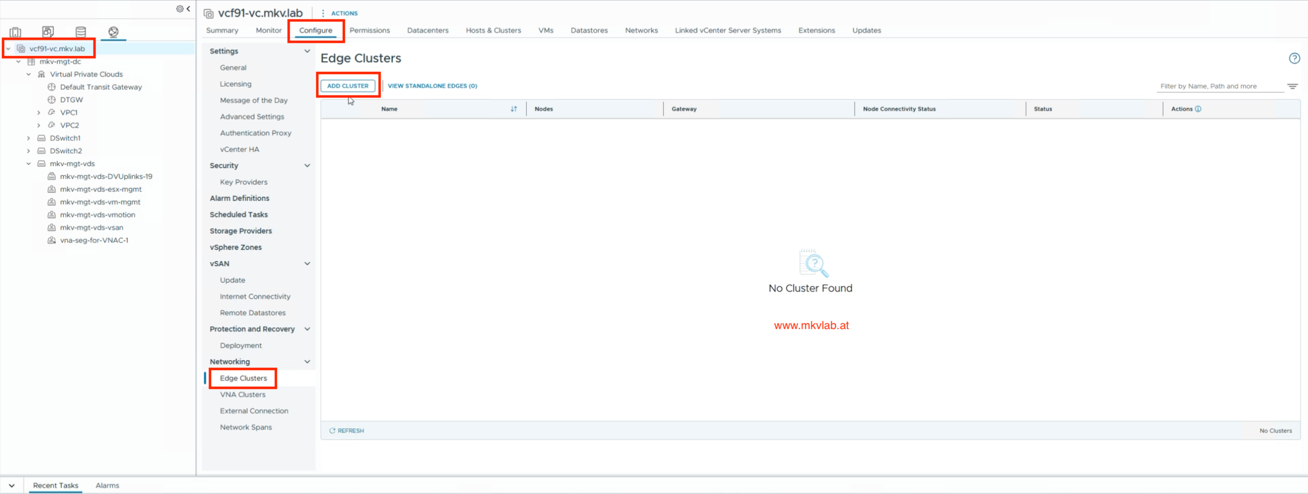 Edge Clusters page before deployment
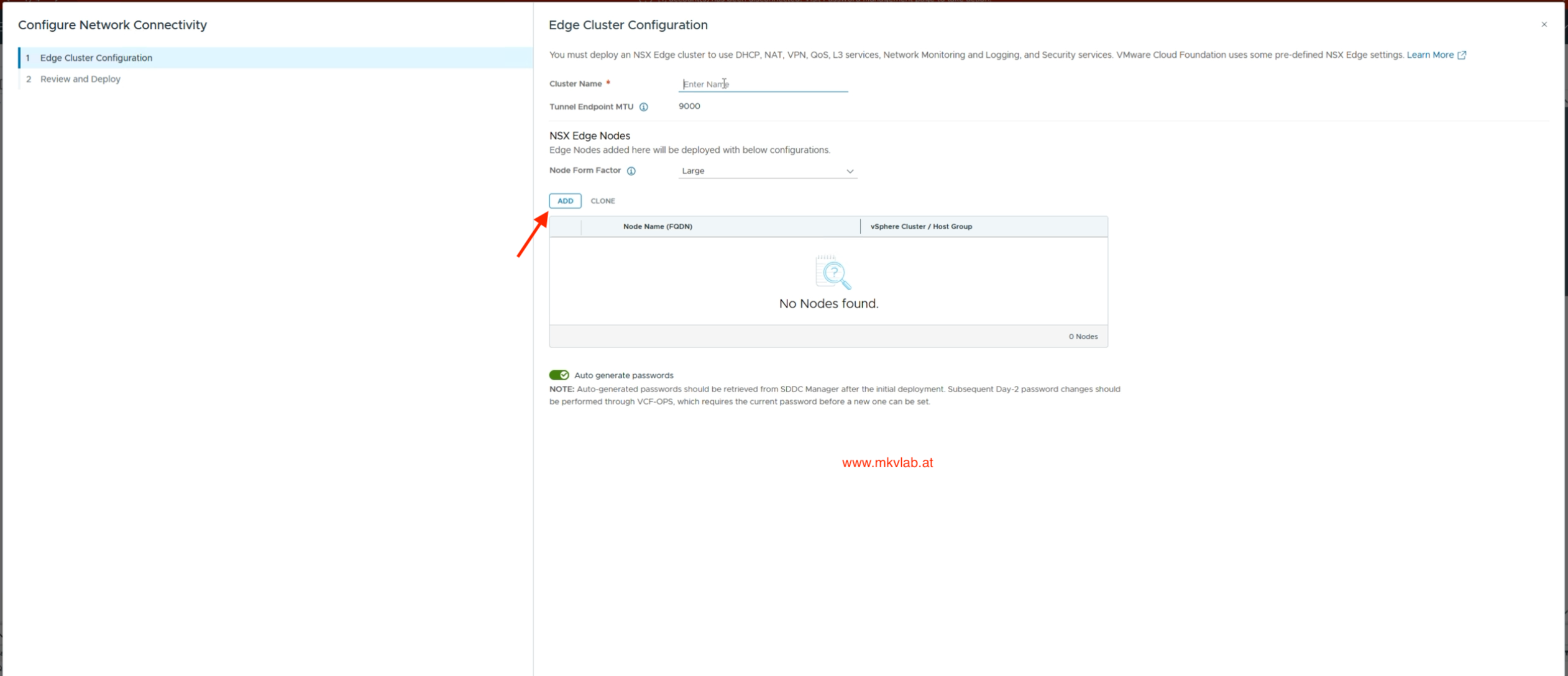 Configure the NSX Edge cluster
For the Edge node, I selected the appropriate vSphere cluster and datastore. I assigned a static management address of 192.168.110.21/24, with 192.168.110.254 as the default gateway, and used the appropriate management port group.
The host overlay configuration supplies the Edge TEP settings. In the screenshots, the TEP VLAN is 111, with addresses allocated from the mkv-mgt-tep01 IP pool with IP range 192.168.111.11-30.
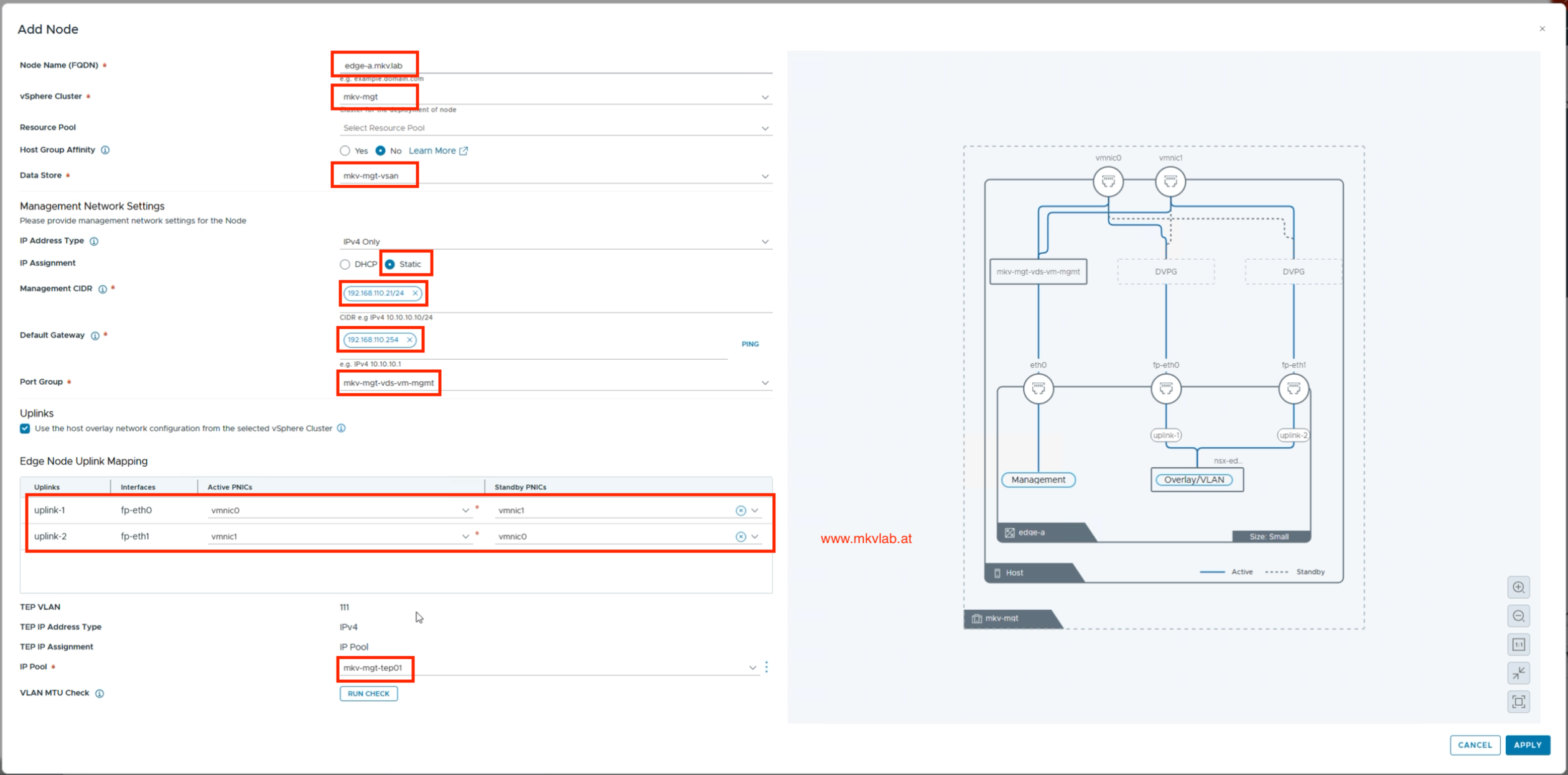 Add the Edge node and configure placement, management, and TEP settings
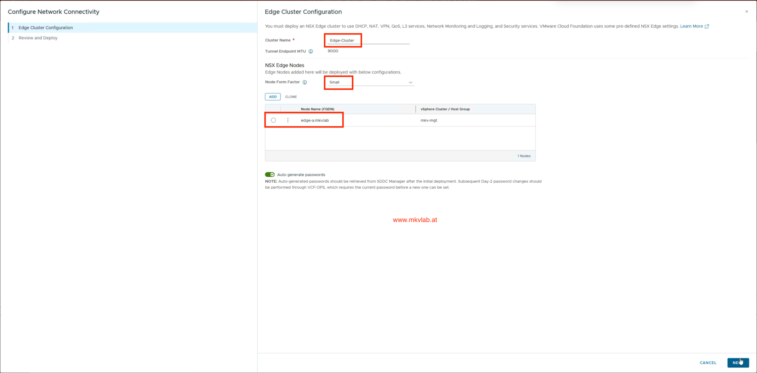 Review the Edge cluster configuration before deployment
After submitting the configuration, I monitored the deployment from the Edge Clusters page. The node initially showed Deploying VM; I continued only after the cluster and node reported Success and the node connectivity status was Up.
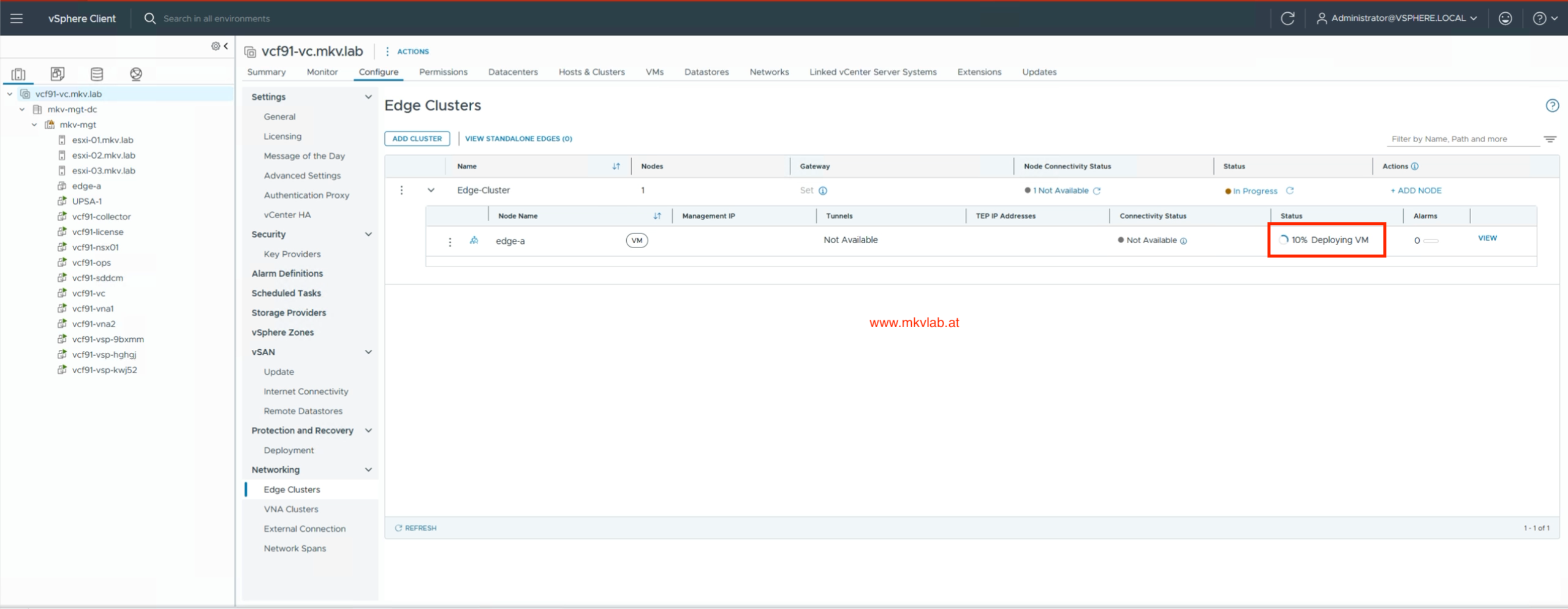 Edge deployment in progress
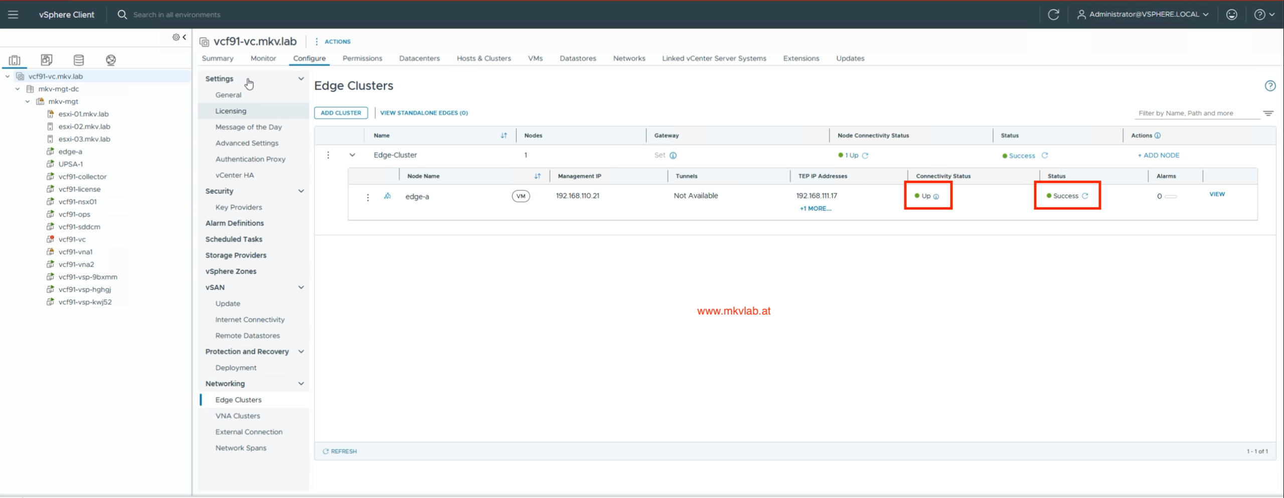 The Edge cluster and node report Success
Step 2: Prepare transport zones and uplink segments
Next, I checked the transport zones in NSX:
1
NSX Manager > System > Fabric > Transport Zones
The lab already had an overlay transport zone, MKvLab-Overlay-TZ. I also created a VLAN transport zone, MKvLab-VLAN-TZ, for the external uplink segments.
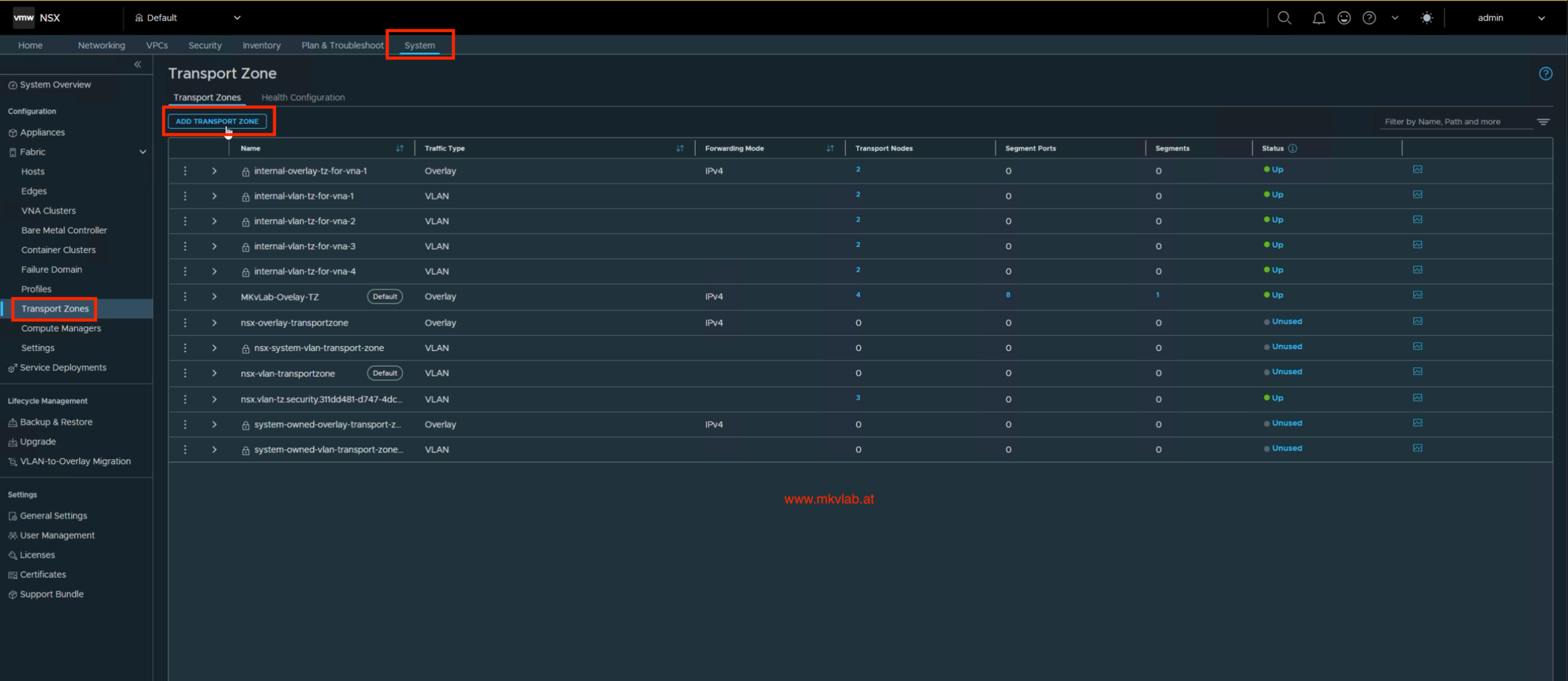 Review the transport zones available in NSX
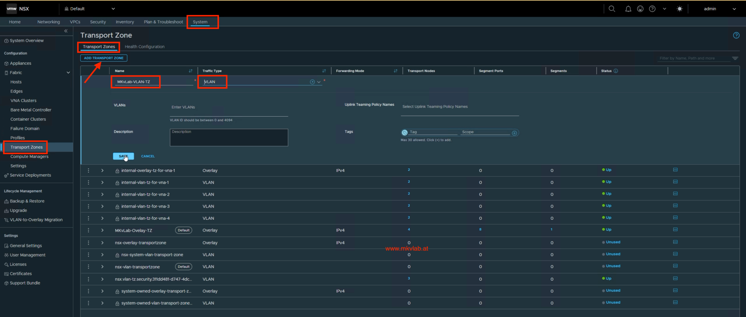 Create a Transport Zone for the Tier-0 uplinks
Under Networking > Segments, I created two VLAN-backed segments in MKvLab-VLAN-TZ:
| Segment | VLAN | Purpose |
|---|---|---|
Left-Uplink |
117 |
First Tier-0 external interface |
Right-Uplink |
118 |
Second Tier-0 external interface |
Neither segment is connected to a gateway at this stage; the Tier-0 external interfaces will connect to them later.
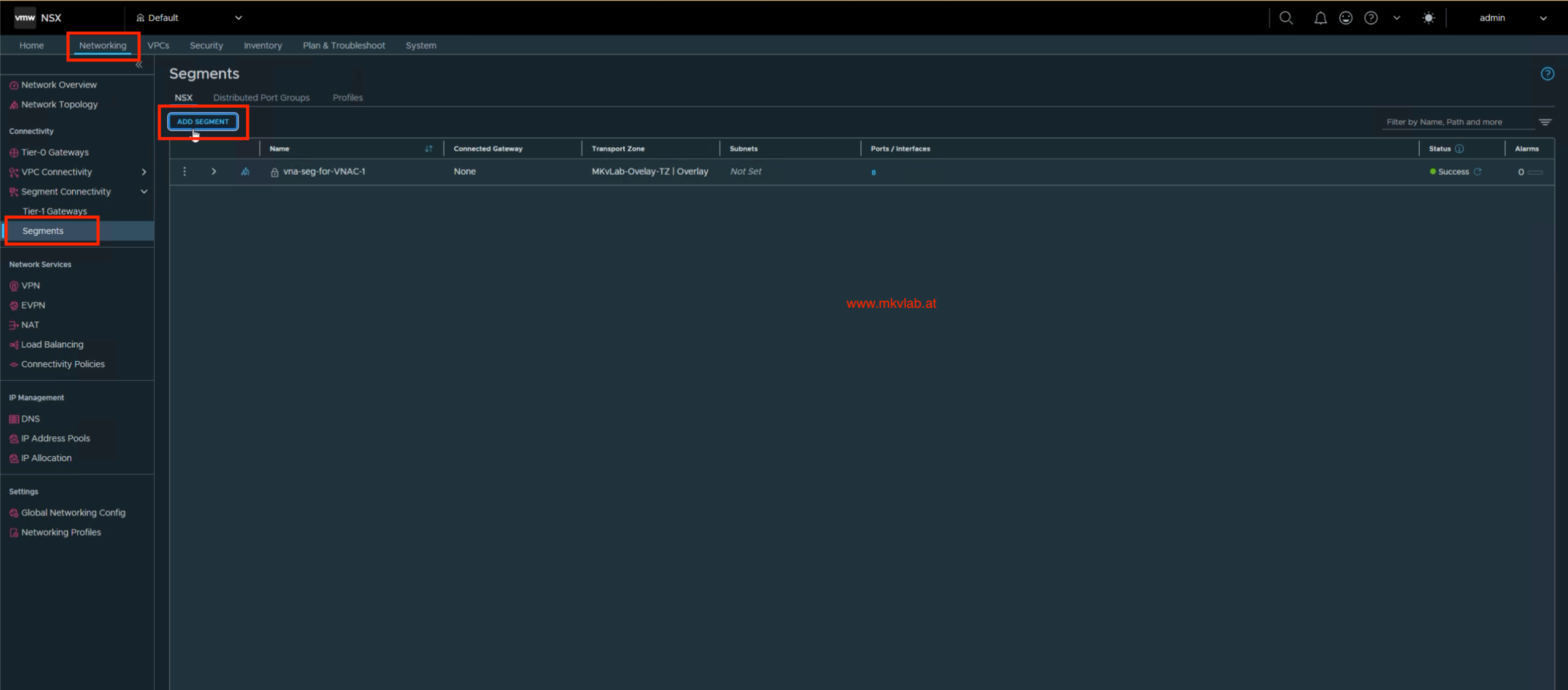 Segments page before adding the uplink segments
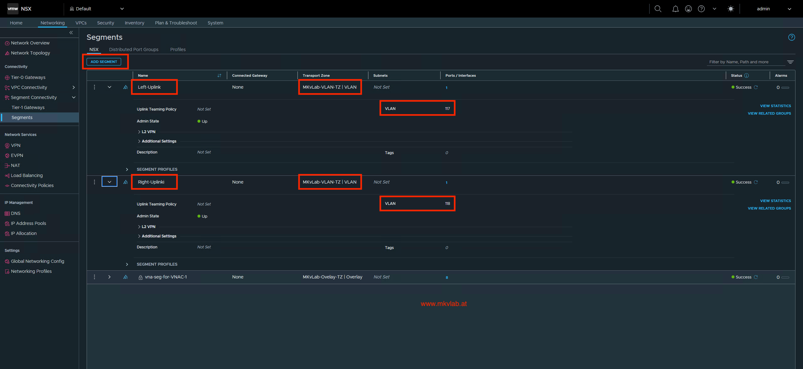 The two VLAN-backed uplink segments
Step 3: Create the Tier-0 Gateway
In NSX Manager, navigate to:
1
Networking > Tier-0 Gateways > Add Gateway > Tier-0
I created the Tier-0 Gateway as T0, selected Active-Active HA mode, and assigned Edge-Cluster.
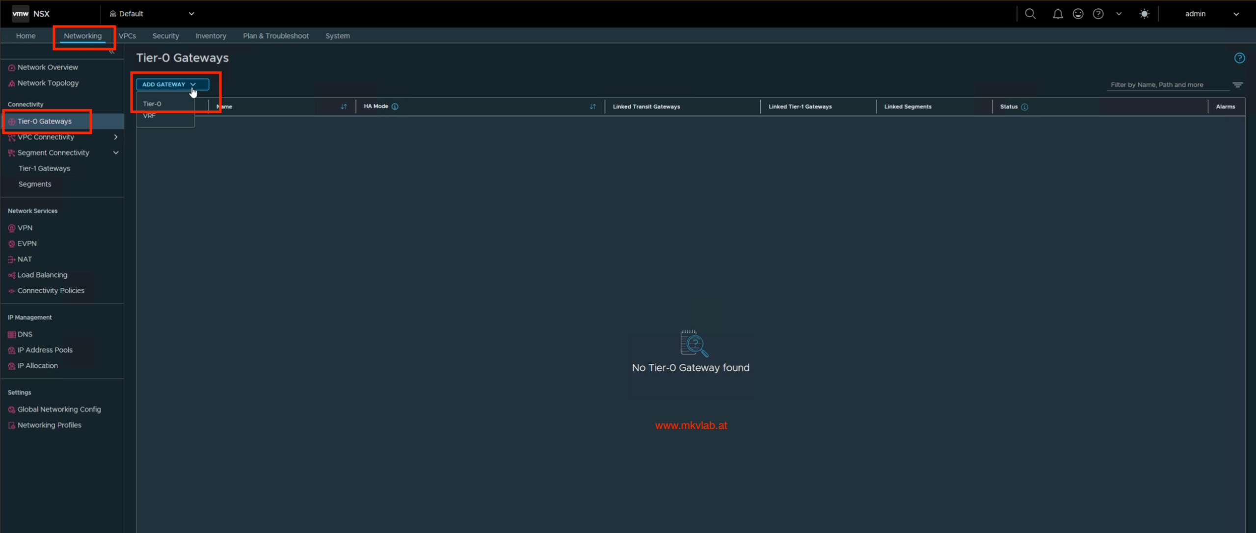 Start creating the Tier-0 Gateway
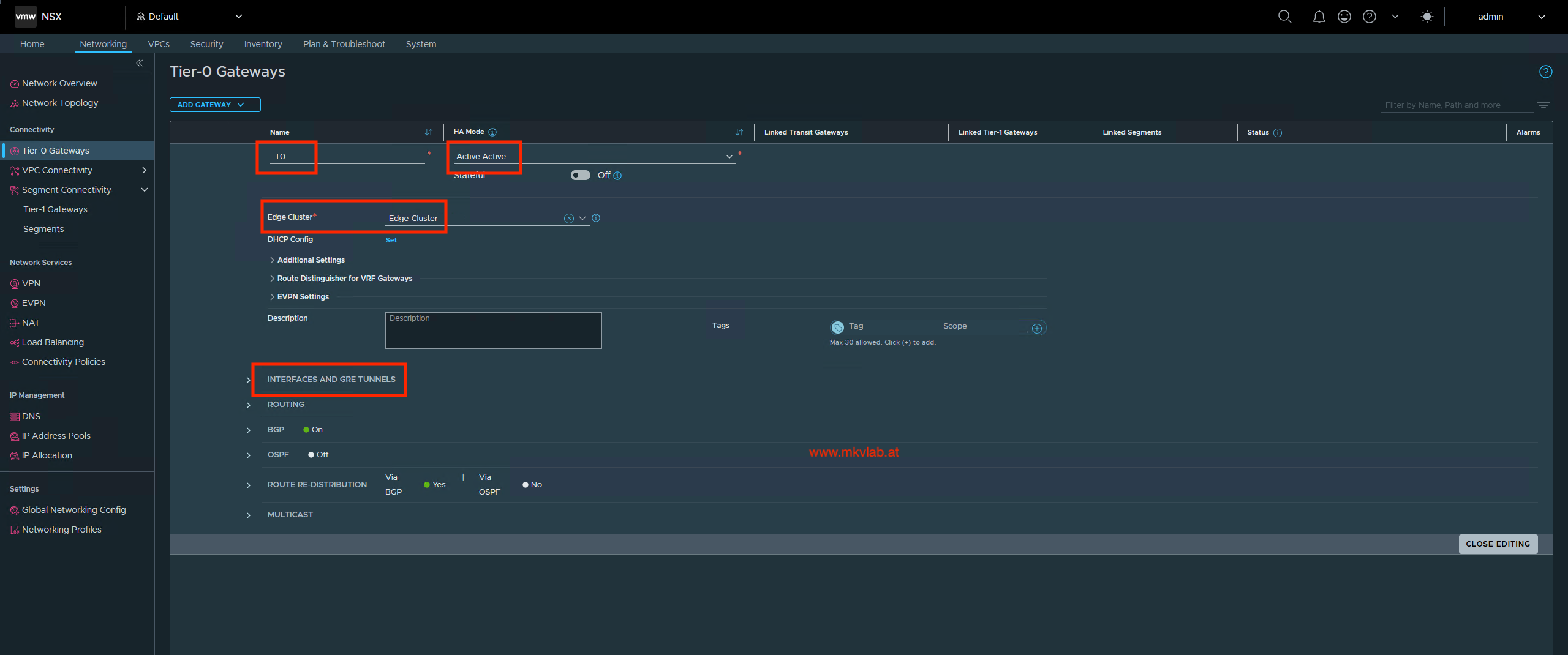 Assign the Edge cluster to
 T0
Next, add the external interfaces:
| Interface | Edge node | IP address | Connected segment |
|---|---|---|---|
Left-Uplink |
edge-a |
192.168.117.11/24 |
Left-Uplink |
Right-Uplink |
edge-a |
192.168.118.11/24 |
Right-Uplink |
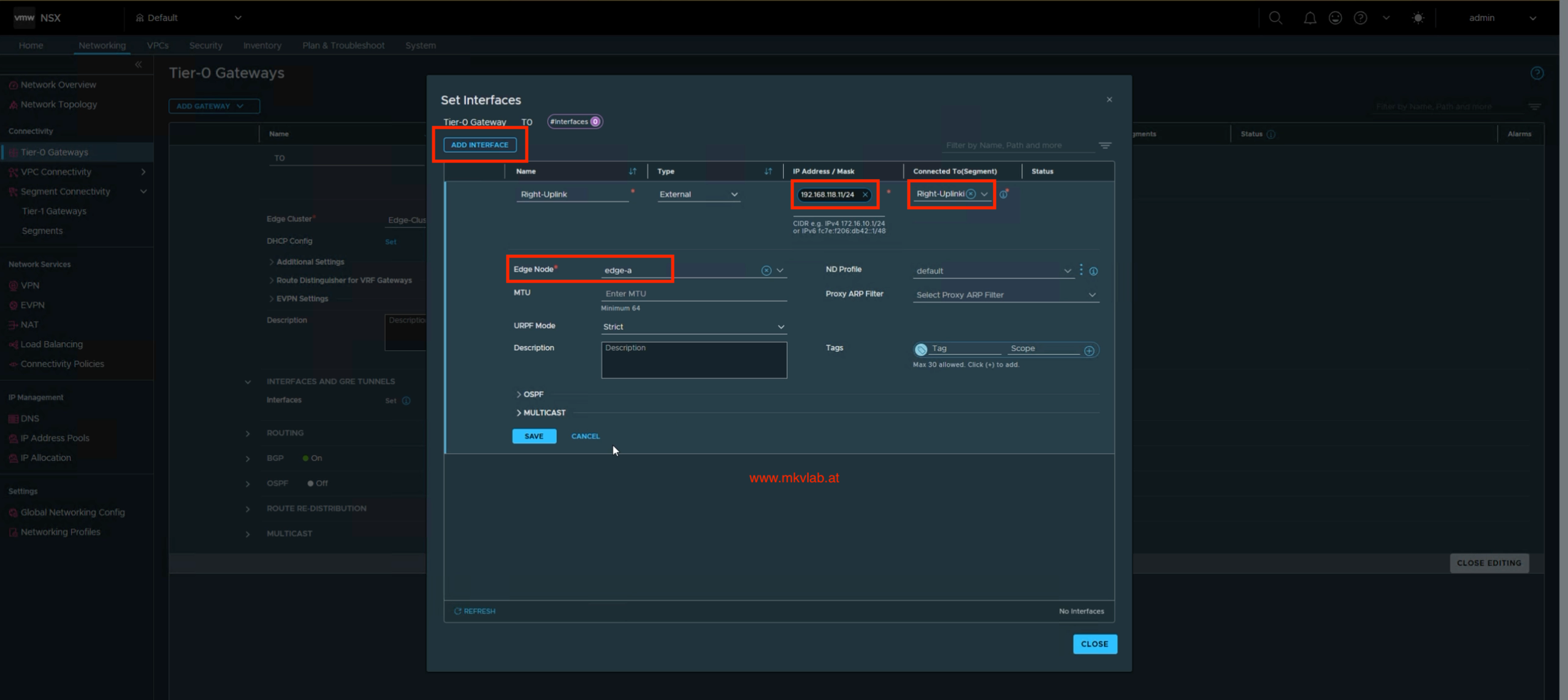 Add an external interface and connect it to its VLAN segment
Troubleshooting interface realization
My first attempt did not realize the interfaces successfully. The error indicated that the Edge transport node needed to belong to the transport zone used by the linked logical switch port. In other words, creating the VLAN transport zone and segments was not enough: the Edge node also had to be configured to use that transport zone.
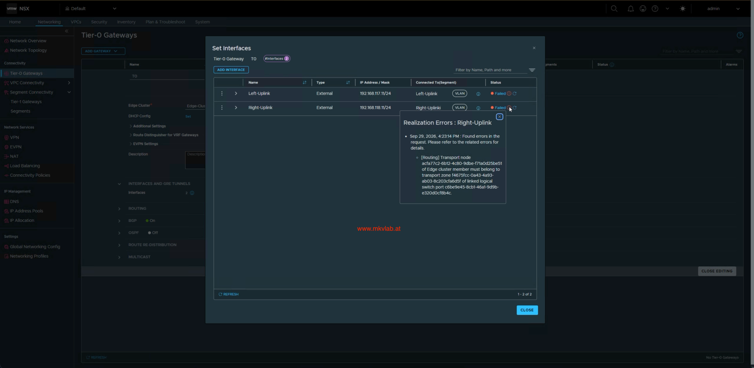 The interface realization error points to a transport-zone mismatch
I edited edge-a and checked its Edge Node Uplink Mapping. The corrected mapping included both MKvLab-Overlay-TZ and MKvLab-VLAN-TZ on the Edge node’s overlay/VLAN switch.
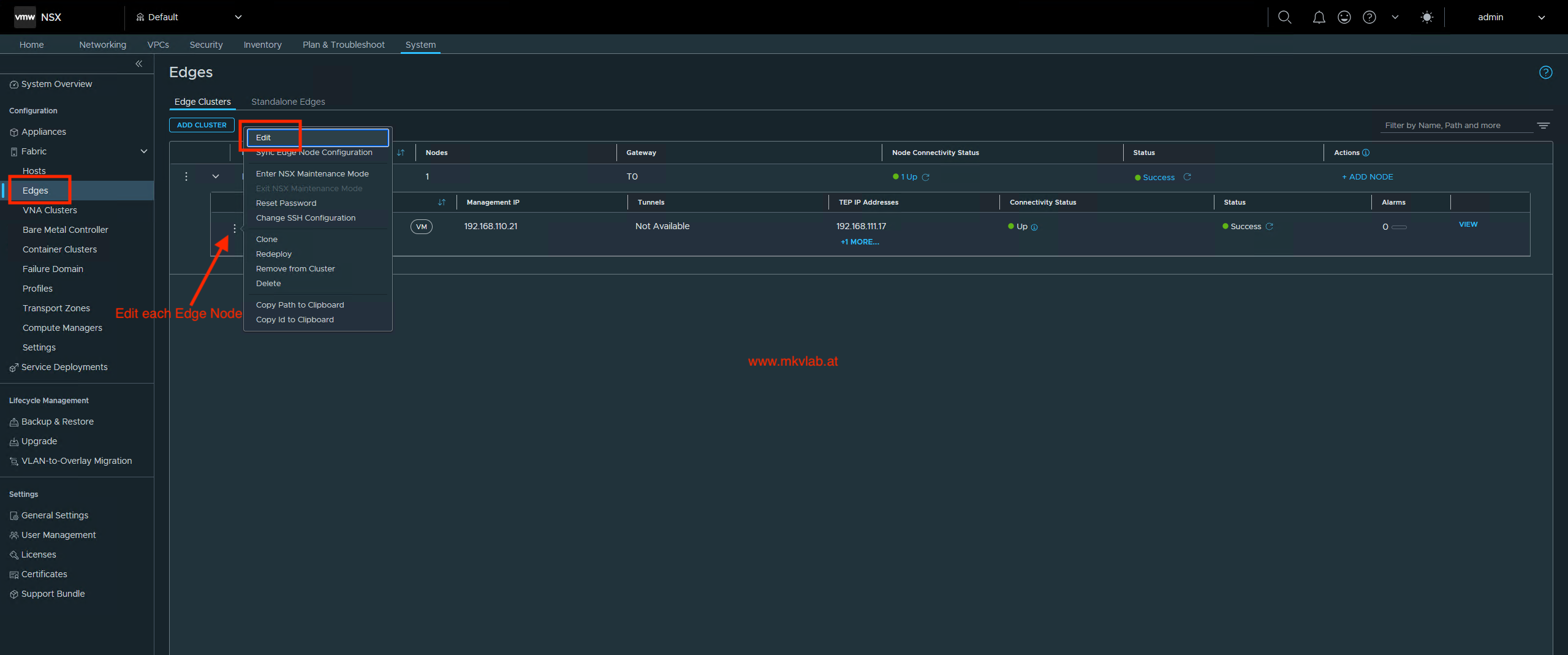 Edit Edge node
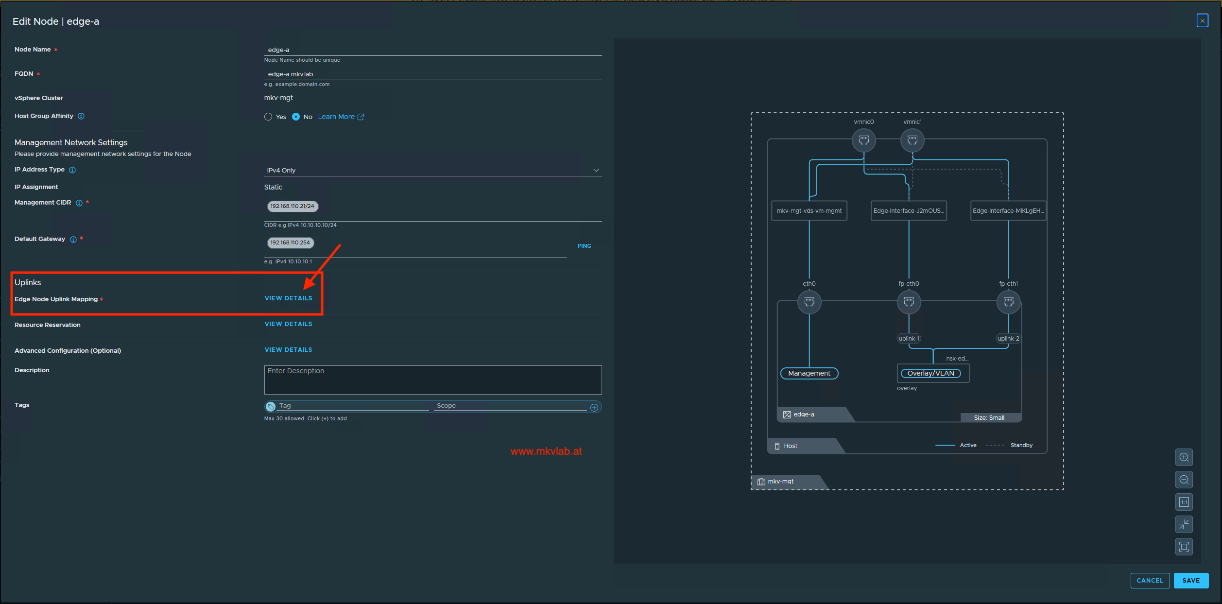 Review the Edge node networking configuration
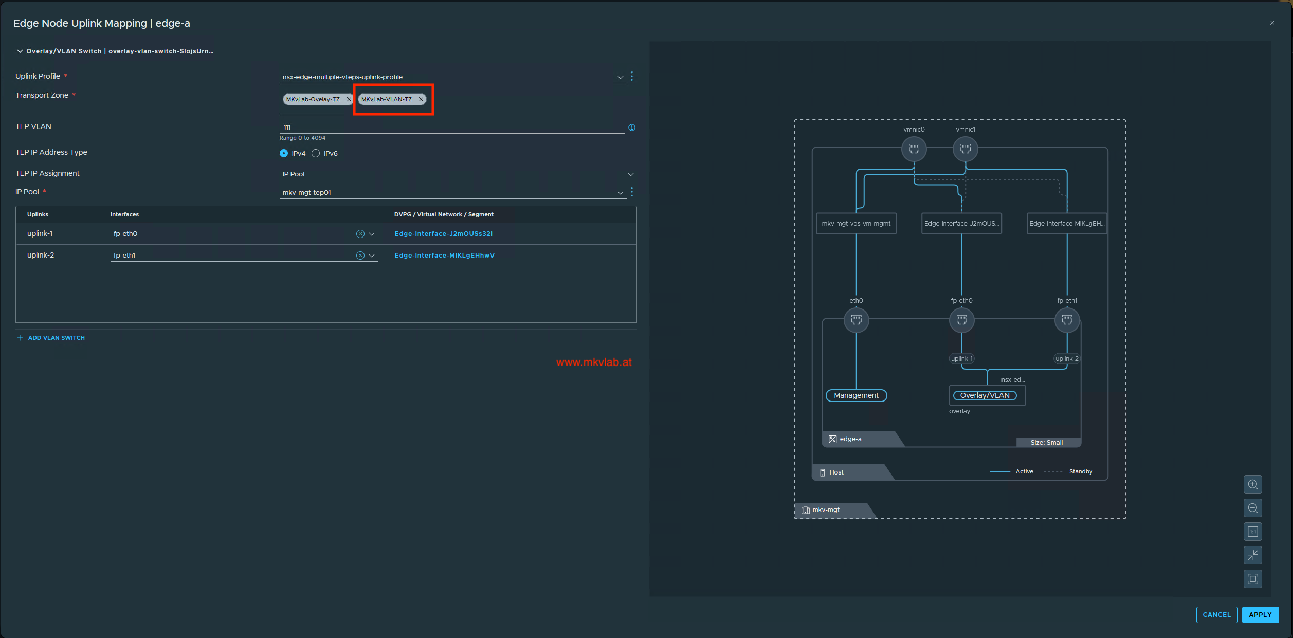 Add the VLAN transport zone to the Edge node uplink mapping
After correcting the mapping and allowing the configuration to realize, both Tier-0 external interfaces showed Success.
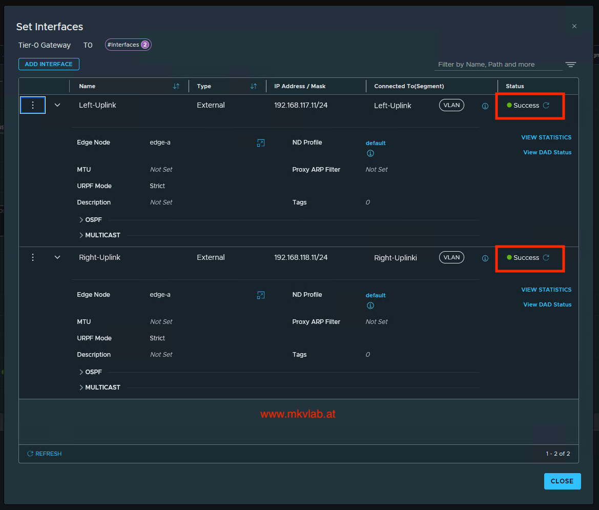 Both external Tier-0 interfaces report Success
Troubleshooting tip: If a Tier-0 interface fails to realize on a VLAN segment, check the segment’s transport zone and the Edge node’s transport-zone membership before troubleshooting the upstream switch.
Step 4: Configure BGP
With the external interfaces available, I configured BGP neighbors on T0. The final screenshots show a local AS of 300 and two neighbors using remote AS 200.
| Neighbor | Tier-0 source address | Remote AS |
|---|---|---|
192.168.117.254 |
192.168.117.11 |
200 |
192.168.118.254 |
192.168.118.11 |
200 |
The screenshots show an earlier Tier-0 edit with a different local AS. The lab’s later configuration uses 300, so confirm that the AS configured on the upstream peers matches the final Tier-0 design.
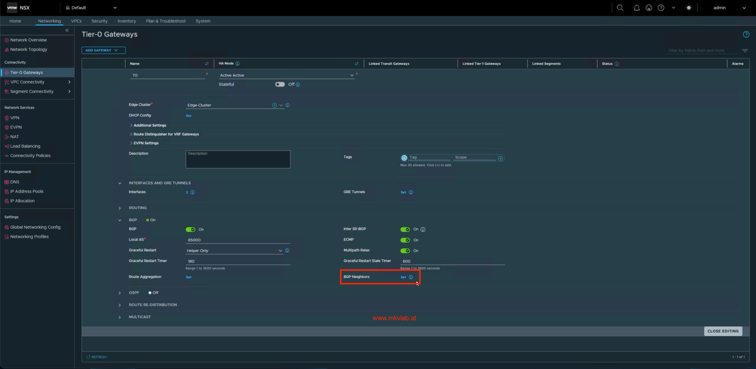 Enable BGP on the Tier-0 Gateway
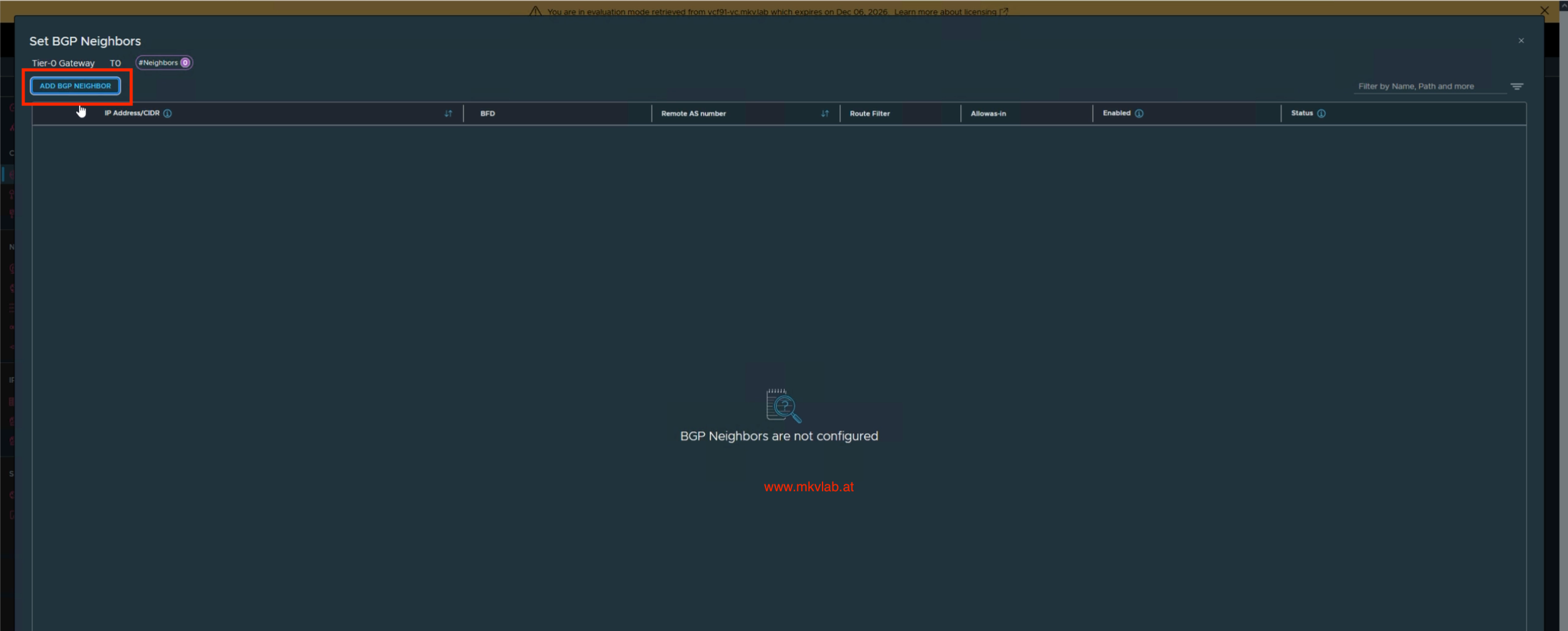 No BGP neighbors have been added yet
For each neighbor, I set the upstream IP address, remote AS, and the Tier-0 interface address to use as the source.
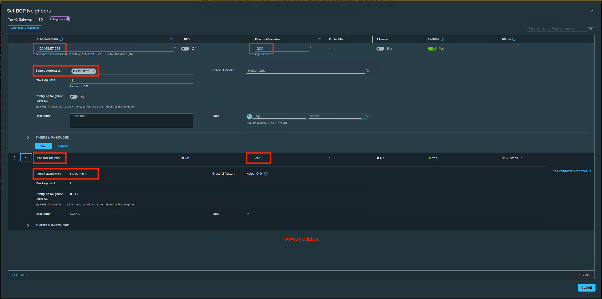 Configure an upstream BGP neighbor
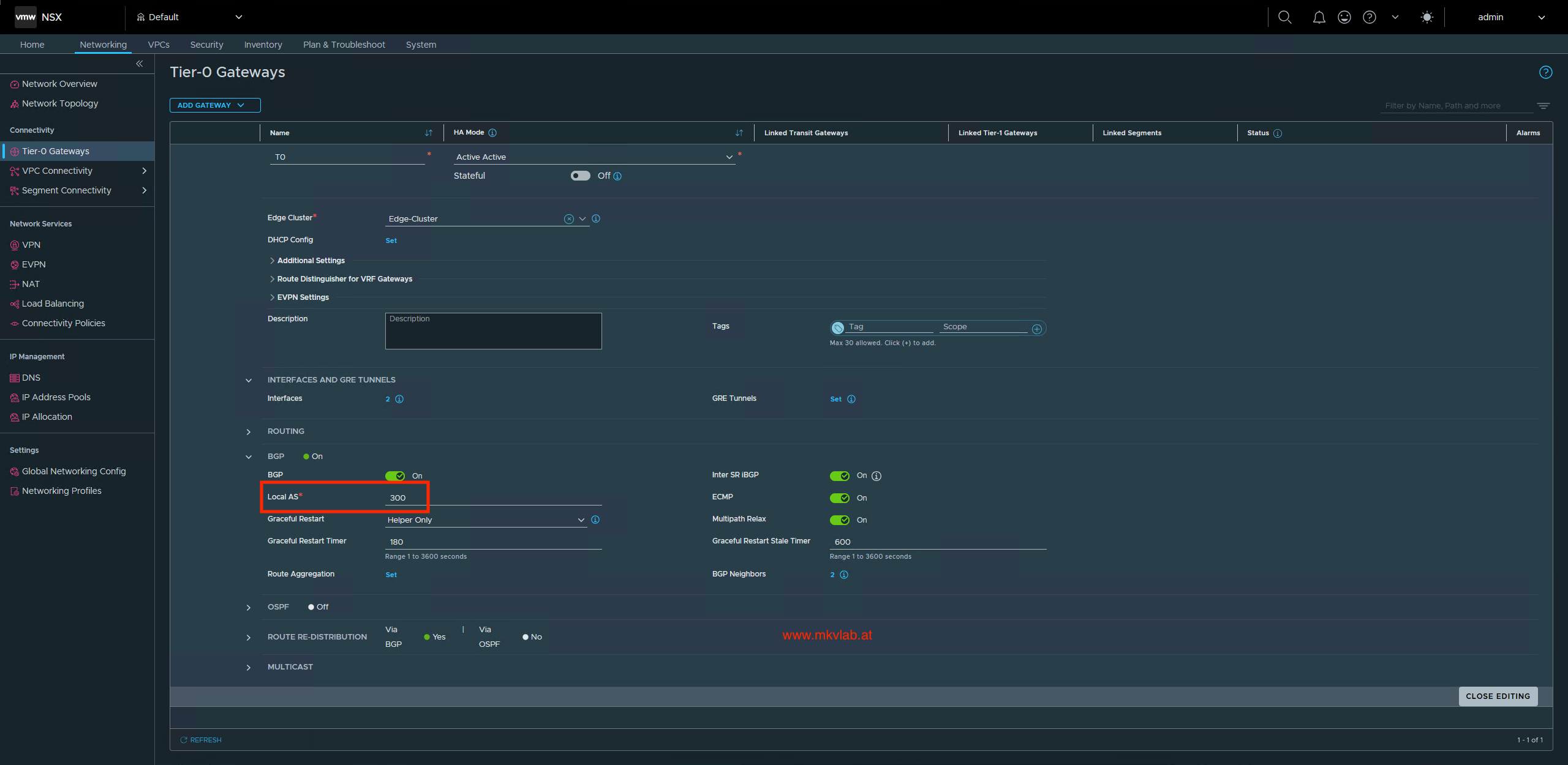 The later Tier-0 configuration shows local AS
 300
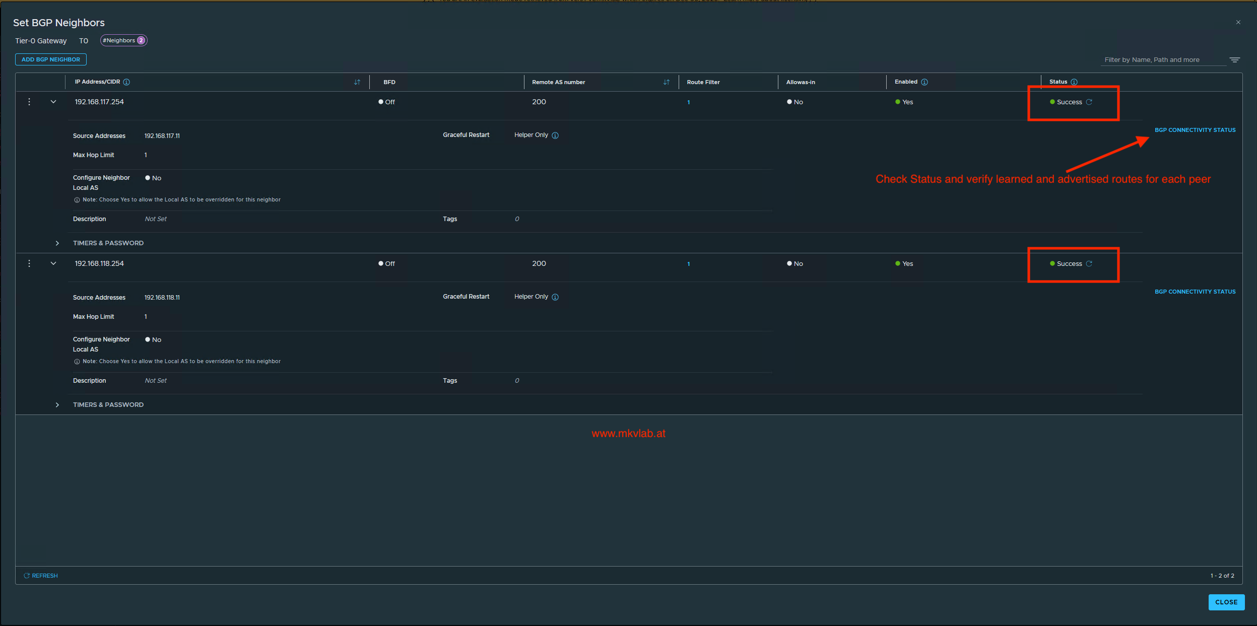 Both neighbor objects are configured successfully
Important: A configuration status of Success confirms that NSX accepted and realized the neighbor configuration; it is not, by itself, proof that the BGP sessions are established. Check the BGP Connectivity Status for each peer and verify learned and advertised routes.
Step 5: Prepare the VPC IP blocks
The CTGW needs external IP space for VPC connectivity and a separate private transit gateway IP block.
For this lab, I used:
| IP block | CIDR | Use |
|---|---|---|
External IP Block 92 |
192.168.92.0/24 |
External addresses and the public VPC subnet |
Private Transit Gateway IP Block |
172.31.255.0/24 |
Private transit gateway addressing |
The external block must be reachable through the upstream routing design. Creating the IP block in vCenter does not, on its own, ensure that the upstream network has a return route to it.
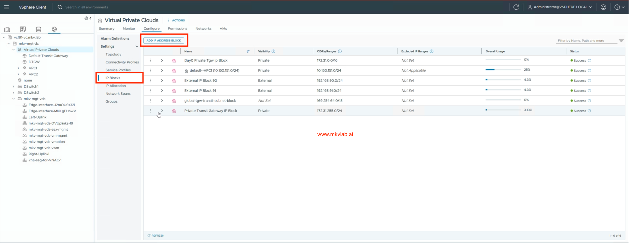 Add new IP Address Block
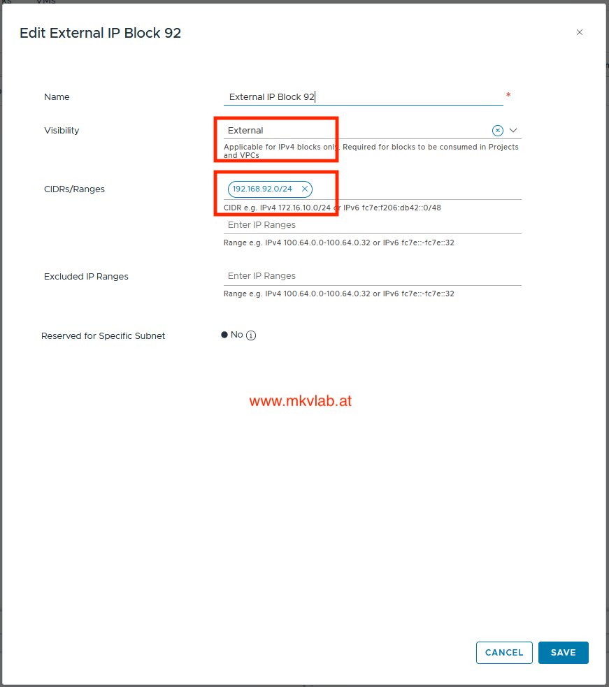 External IP Block 92 uses
 192.168.92.0/24
Step 6: Create the CTGW
In the vSphere Client, select Virtual Private Clouds, open Actions, and choose New Transit Gateway.
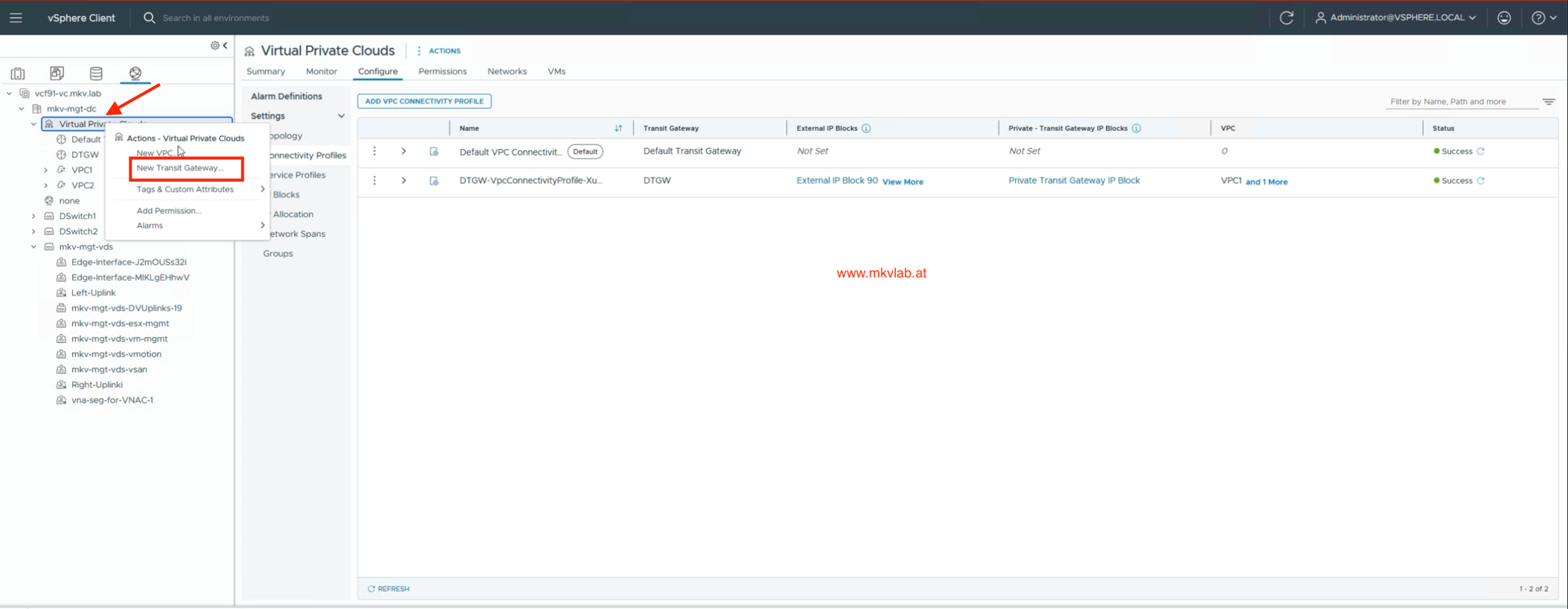 Start the New Transit Gateway wizard
Name the gateway CTGW and choose Centralized Connection. This option attaches the Transit Gateway to a Tier-0 Gateway for external connectivity. I selected the existing Edge-Cluster in the gateway settings.
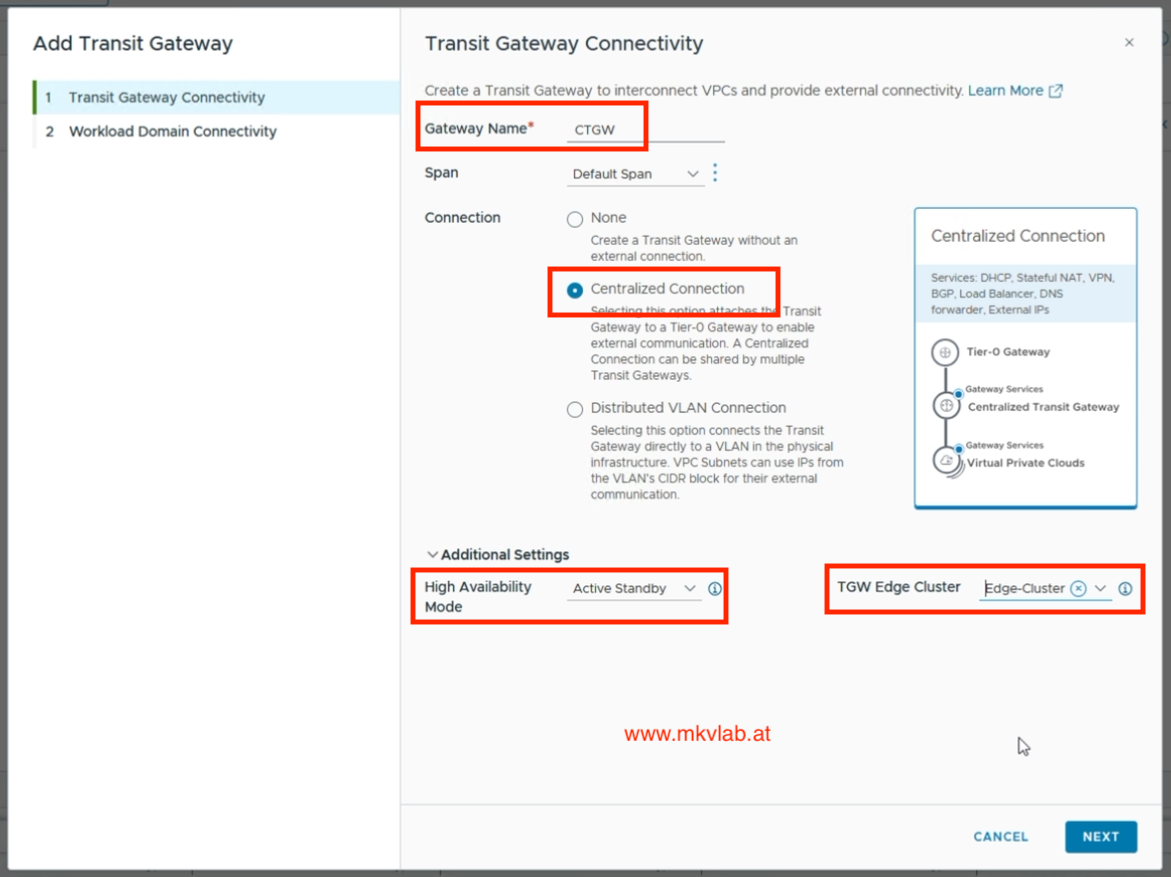 Create Transit Gateway with a centralized connection
Important: When creating the CTGW, choose its High Availability Mode based on the services you need. Active-Active distributes CTGW traffic across Edge nodes but does not support stateful services such as NAT. Active-Standby supports stateful services, including NAT. In this lab, I selected Active-Standby because I enabled Default Outbound NAT.
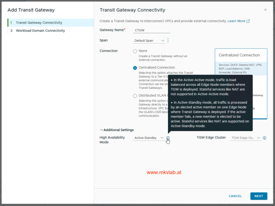 High Availability Mode
On the Workload Domain Connectivity page, I selected T0, chose External IP Block 92 and the Private Transit Gateway IP Block, and enabled Default Outbound NAT.
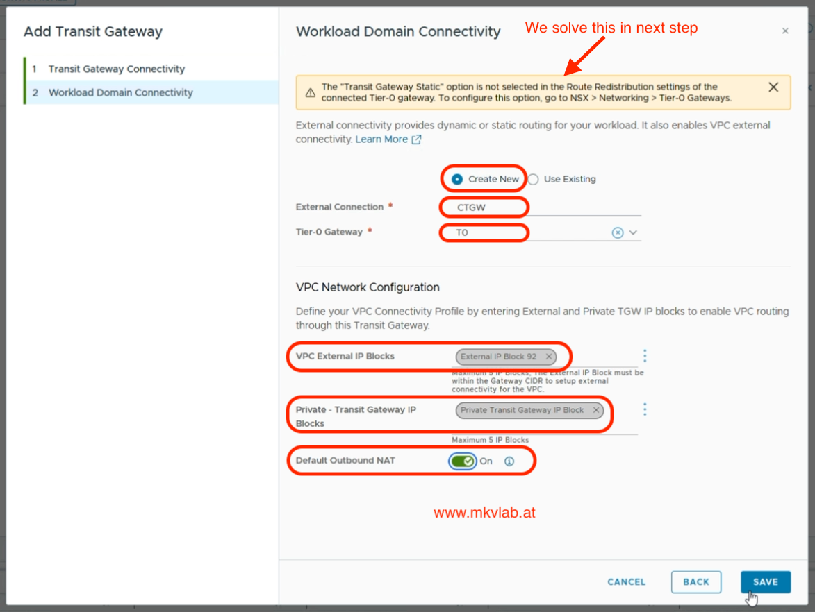 Select the Tier-0 Gateway, IP blocks, and Default Outbound NAT
Once the CTGW was created, vCenter showed a new connectivity profile associated with CTGW, External IP Block 92, and the private transit gateway IP block.
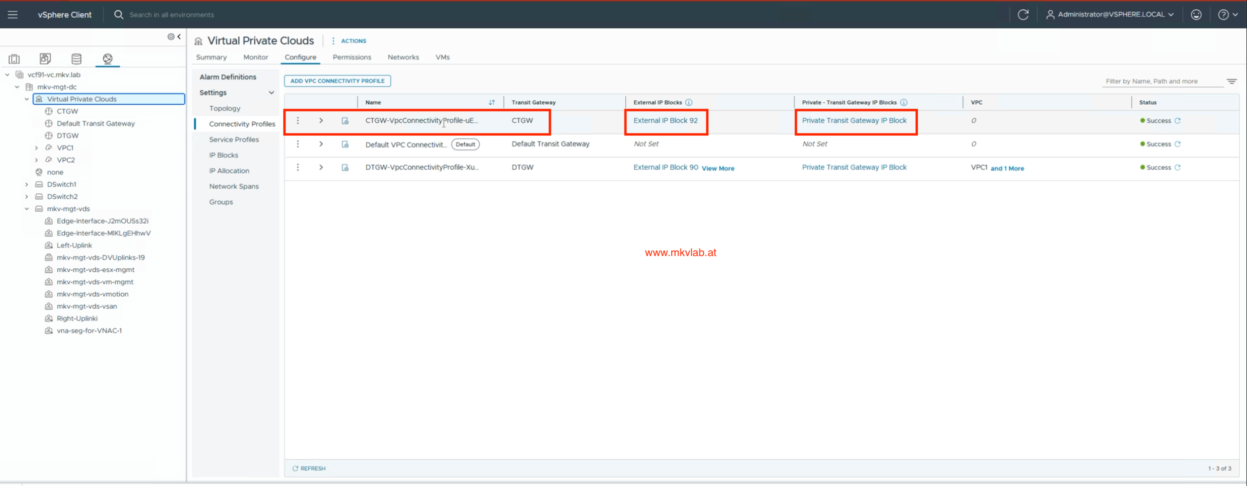 CTGW has been created
Fix the route redistribution warning
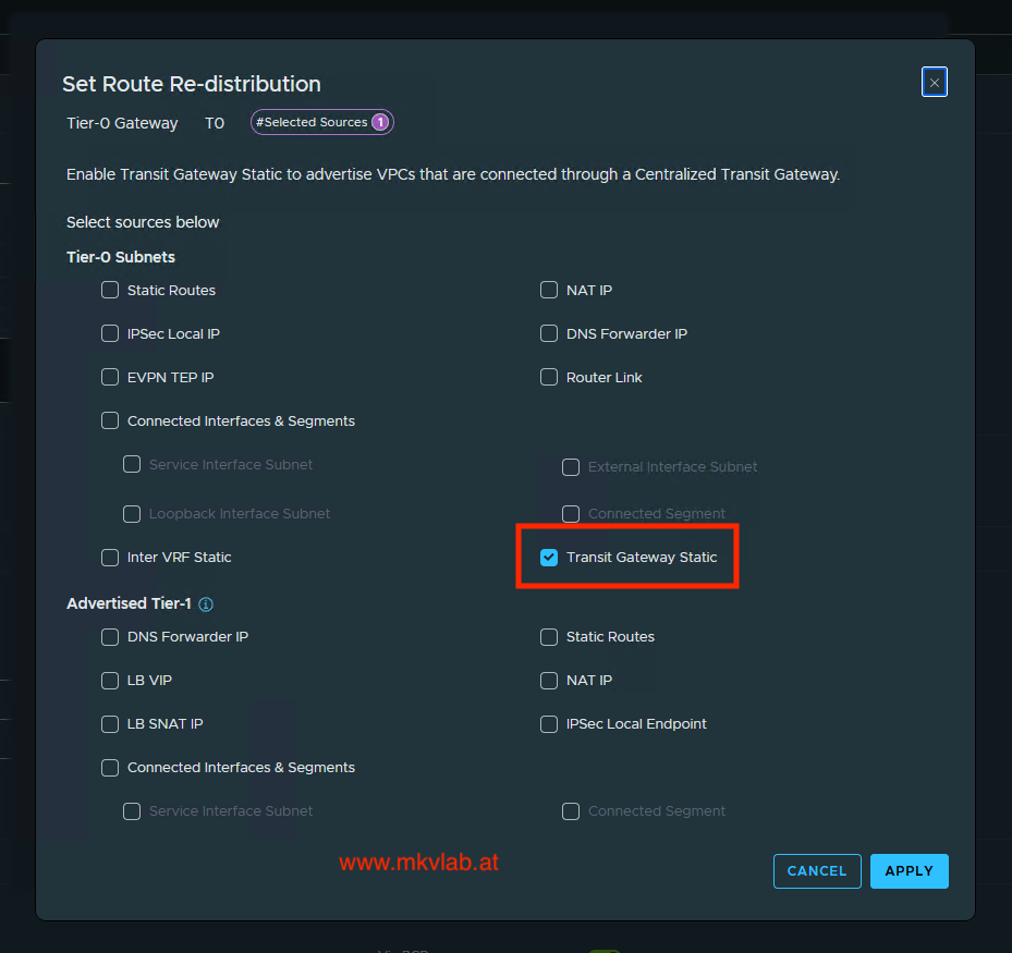
During CTGW creation, the wizard displayed a warning that Transit Gateway Static was not selected in the connected Tier-0 Gateway’s route redistribution settings. I went back to T0 in NSX Manager and updated its BGP route redistribution configuration.
Under Route Re-distribution, add or edit a rule whose destination protocol is BGP. In its redistribution sources, select Transit Gateway Static. The UI explains that this source is used to advertise VPCs connected through a Centralized Transit Gateway.
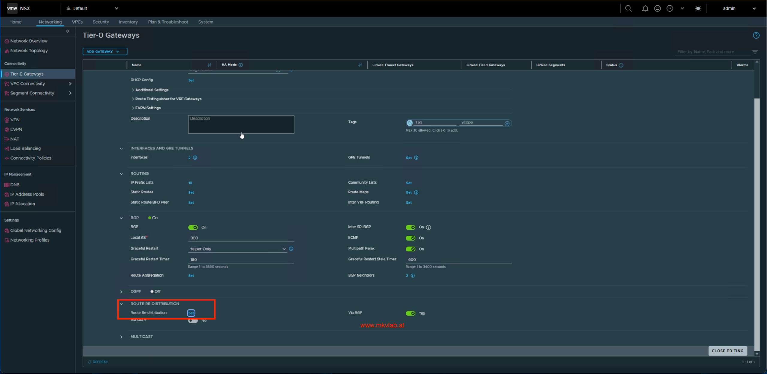 Edit T0 to add route redistribution
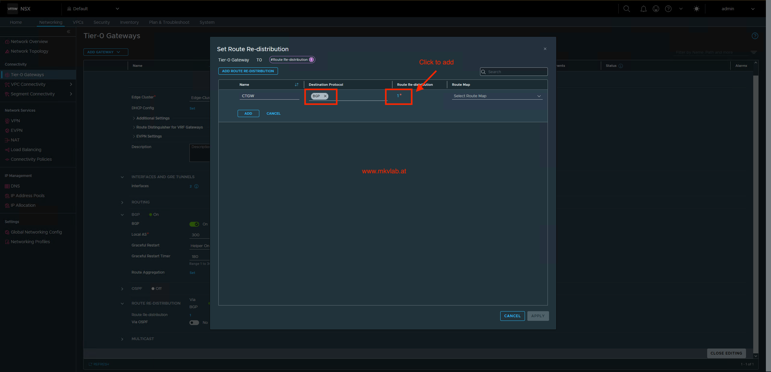 Configure a route redistribution rule with BGP as its destination protocol
 Select
 Transit Gateway Static as a redistribution source
Important: Do not ignore this warning if you expect the upstream BGP peers to learn routes for the connected VPC networks. After changing redistribution, verify the actual advertised prefixes and confirm that the upstream network has the routes it needs.
After adding Re-distribution, the connected VPC public networks, will be advertised to upstream router.
Step 7: Create a VPC and public subnet
To consume the new CTGW, I created VPC3 from the Virtual Private Clouds inventory and selected the CTGW connectivity profile under Advanced Settings. The private VPC CIDR for this lab is 10.150.152.0/24.
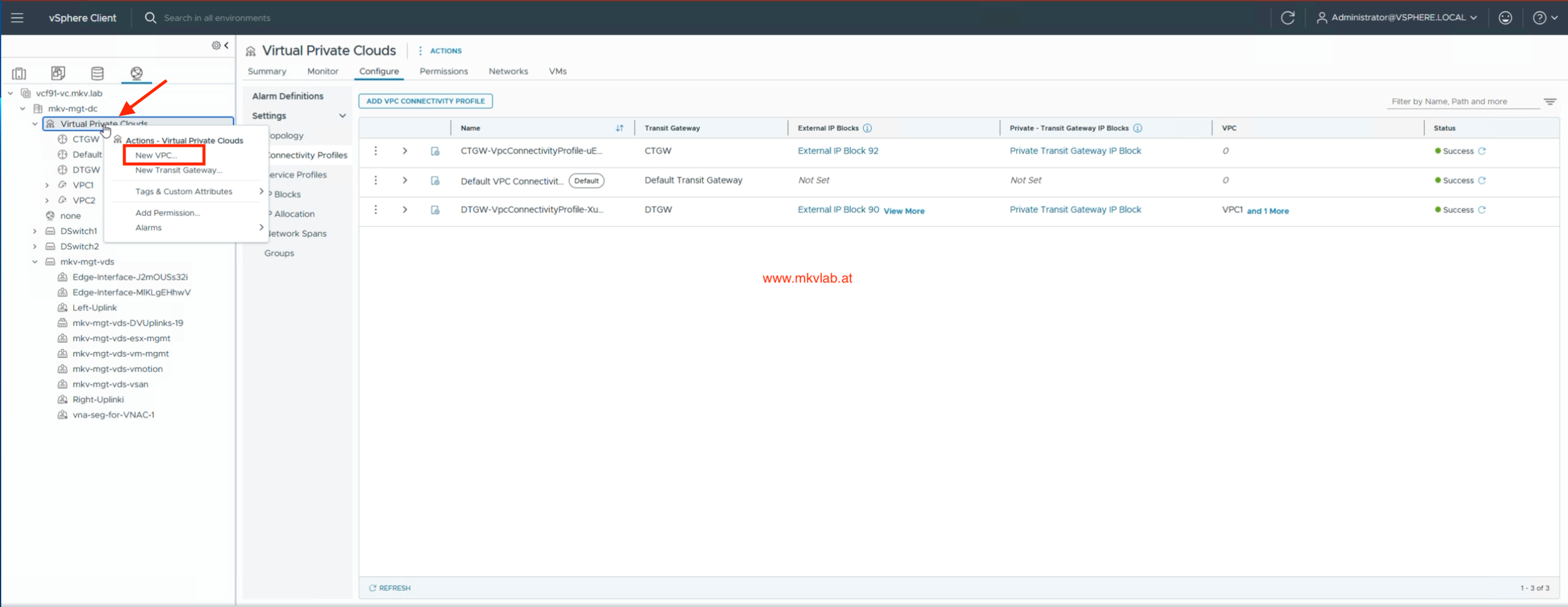 Start creating a VPC
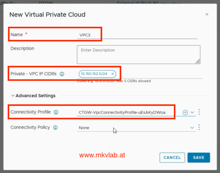 Create
 VPC3 with its private CIDR and CTGW connectivity profile
I then configured VPC3-Public as a Public subnet using External IP Block 92. In the screenshot, automatic subnet allocation is enabled, the selected size is 8 IPs (/29), VPC Gateway Connectivity is enabled, and DHCP Server is selected.
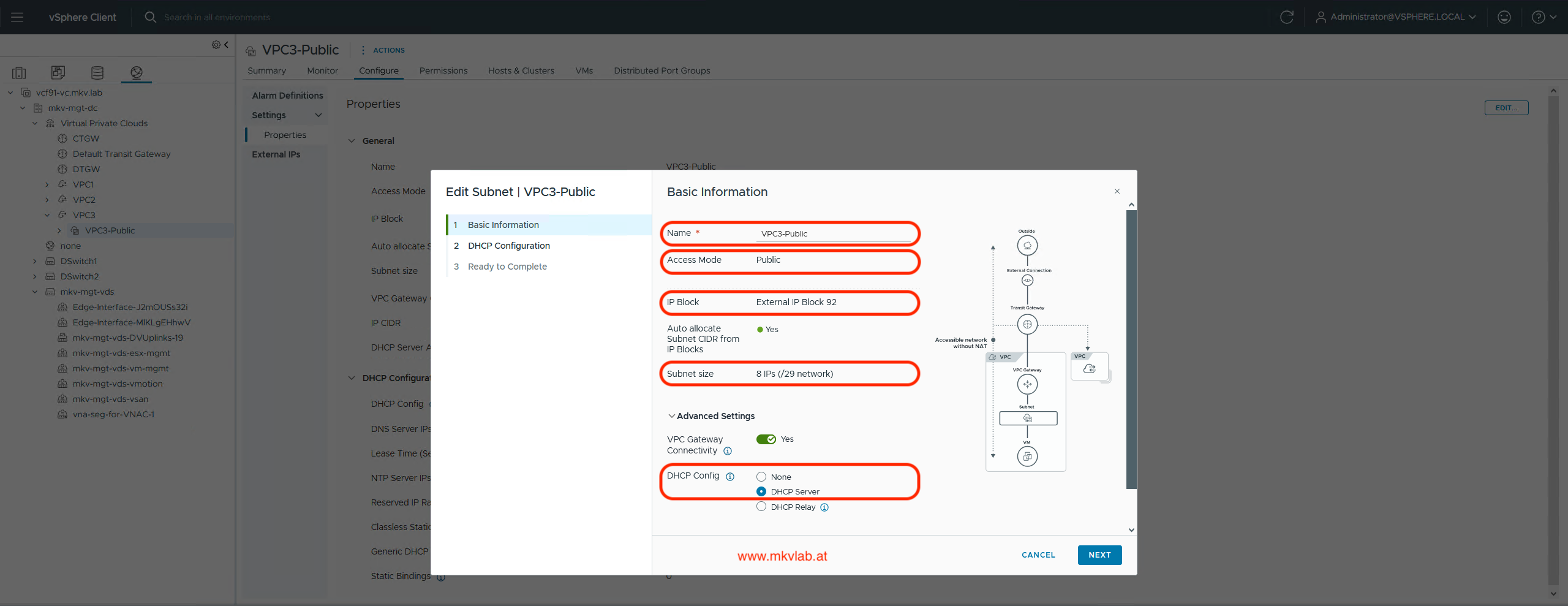 Configure the public VPC subnet from External IP Block 92
The public subnet uses addresses from the external block rather than the private 10.150.152.0/24 VPC CIDR. For workloads to communicate beyond the VPC, the upstream network must also have a working route back to the allocated public subnet, and the applicable firewall policy must allow the traffic.
Validation
Before testing an application VM, I check the deployment in this order:
- Confirm that the Edge cluster and
edge-areport Success and Up. - Confirm that both Tier-0 interfaces report Success.
- Check that both BGP sessions are established, not merely configured.
- Verify that the expected VPC or public subnet routes are advertised to the upstream peers.
- Confirm that
CTGW, its connectivity profile,VPC3, andVPC3-Publicreport healthy configuration status. - Test traffic from a VM on the public subnet and verify its return path through the upstream network.
If a route is missing, I check the Transit Gateway Static redistribution source and the upstream BGP route table first. If an interface fails to realize, I return to the Edge uplink mapping and transport-zone configuration.
Key takeaways
- A CTGW provides VPC external connectivity through an Edge-backed Tier-0 Gateway.
- The Edge node must belong to the transport zone used by its external VLAN segments.
- Tier-0 BGP neighbors and route redistribution are separate configuration steps.
- Transit Gateway Static is the important redistribution source for advertising routes associated with VPCs connected through the CTGW.
- A configured BGP neighbor is not necessarily an established BGP session; validate the control plane and the end-to-end traffic path.